
I’m trying to read a word document using C#. I am able to get all text but I want to be able to read line by line and store in a list and bind to a gridview. Currently my code returns a list of one item only with all text (not line by line as desired). I’m using the Microsoft.Office.Interop.Word library to read the file. Below is my code till now:
    Application word = new Application();
    Document doc = new Document();

    object fileName = path;
    // Define an object to pass to the API for missing parameters
    object missing = System.Type.Missing;
    doc = word.Documents.Open(ref fileName,
            ref missing, ref missing, ref missing, ref missing,
            ref missing, ref missing, ref missing, ref missing,
            ref missing, ref missing, ref missing, ref missing,
            ref missing, ref missing, ref missing);

    String read = string.Empty;
    List<string> data = new List<string>();
    foreach (Range tmpRange in doc.StoryRanges)
    {
        //read += tmpRange.Text + "<br>";
        data.Add(tmpRange.Text);
    }
    ((_Document)doc).Close();
    ((_Application)word).Quit();

    GridView1.DataSource = data;
    GridView1.DataBind();
Dynamic Random Access Memory ( DRAM ) or the half-German term dynamic RAM describes a technology for an electronic memory component with random access ( Random-Access Memory , RAM), which is mainly used in computers , but also in other electronic devices such as printers is used. The storing element is a capacitor that is either charged or discharged. It is accessible via a switching transistor and either read out or written with new content.
The memory content is volatile, i.e. the stored information is lost if there is no operating voltage or if it is refreshed too late.
introduction
A characteristic of DRAM is the combination of a very high data density combined with very inexpensive manufacturing costs. It is therefore mainly used where large amounts of memory have to be made available with medium access times (compared to static RAM , SRAM).
In contrast to SRAMs, the memory content of DRAMs must be refreshed cyclically (refresh). This is usually required every tens of milliseconds . The memory is refreshed line by line. For this purpose, a memory line is transferred in one step to a line buffer located on the chip and from there is written back to the memory line in an amplified manner. Hence the term «dynamic» comes from. In contrast, with static memories such as SRAM, all signals can be stopped without loss of data. Refreshing the DRAM also consumes a certain amount of energy in the idle state. SRAM is therefore preferred in applications where a low quiescent current is important.
Charge in the storage cell capacitors evaporates within milliseconds, but due to manufacturing tolerances, it can persist in the storage cells for seconds to minutes. Researchers at Princeton University managed to forensically read data immediately after a cold start. To be on the safe side , the components are always specified with the guaranteed worst-case value , i.e. the shortest possible holding time.
Storage manufacturers are continuously trying to reduce energy consumption by minimizing losses due to recharging and leakage currents. Both depend on the supply voltage, which for DDR2-SDRAM is 1.8 volts, while DDR-SDRAM is still supplied with 2.5 volts. In the DDR3 SDRAM introduced in 2007 , the voltage was lowered to 1.5 volts.
A DRAM is designed either as an independent integrated circuit or as a memory cell part of a larger chip.
The «random» in random access memory stands for random access to the memory content or the individual memory cells, as opposed to sequential access such as, for example, with FIFO or LIFO memories (organized on the hardware side) .
construction
A DRAM does not consist of a single two-dimensional matrix, as shown in simplified form in the article semiconductor memory . Instead, the memory cells , which on the surface of this are arranged and wired, divided into a sophisticated hierarchical structure. While the internal structure is manufacturer-specific, the logical structure visible from the outside is standardized by the JEDEC industrial committee . This ensures that chips from different manufacturers and of different sizes can always be addressed according to the same scheme.
Structure of a memory cell
The structure of a single DRAM memory cell is very simple, it only consists of a capacitor and a transistor . Today a MOS field effect transistor is used . The information is stored as an electrical charge in the capacitor. Each memory cell stores one bit . While planar capacitors were mostly used in the past, two other technologies are currently used:
- In the stack technology (English stack , Stack ‘ ) of the capacitor is built up across the transistor.
- In the trench technology (English trench , trench ‘ ), the capacitor by etching a 5-10 micron hole (or trench) deep generated in the substrate.
- Schematic structure of the basic technologies for DRAM cells (cross-sections)
-

Planar technology
-

Stacking technology
-
Trench technology with poly-Si plate


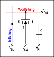
Basic structure of a memory cell from a transistor and a capacitor (1T1C cell)
The upper connection shown in the adjacent figure is either charged to the bit line voltage V BL or discharged (0 V). The lower connection of all capacitors is connected together to a voltage source, which ideally has a voltage of V Pl = 1/2 · V BL . This allows the maximum field strength in the dielectric of the capacitor to be halved.
The transistor (also called the selection transistor) serves as a switch for reading and writing the information from the cell. For this purpose, via the word line (English word line a positive voltage) to the gate terminal «G» of the n-MOS transistor V WL applied. Characterized a conductive connection between the source ( «S») and the drain regions is ( «D») was prepared which the cell capacitor to the bit line (English bitline connects). The substrate connection “B” ( bulk ) of the transistor is connected either to the ground potential or to a slightly negative voltage V Sub to suppress leakage currents.
Due to their very simple structure, the memory cells require very little chip area. The design-related size of a memory cell is often given as the multiple of the square area F² of the smallest feasible structure length (“ minimum feature size ” or F for short): A DRAM cell today requires 6 or 8 F², while an SRAM cell requires more than 100 F² . Therefore, a DRAM can store a much larger number of bits for a given chip size. This results in much lower manufacturing costs per bit than with SRAM . Among the types of electronic memory commonly used today, only the NAND flash has a smaller memory cell with around 4.5 F² (or 2.2 F² per bit for multilevel cells).
Structure of a memory line («Page»)

Interconnection of several memory cells to form a memory line
Further by connecting the memory cells to a word line to obtain a memory line , commonly referred to as side (English page ) is referred to. The characteristic of a row is the property that when a word line (shown in red) is activated, all the associated cells simultaneously output their stored content to the bit line assigned to them (shown in blue). A common page size is 1 Ki , 2 Ki, 4 Ki (…) cells.
Structure of a cell field
Two-dimensional interconnection of memory cells to form a cell field
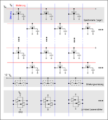
The memory cells are interconnected in a matrix arrangement: ‘word lines’ connect all control electrodes of the selection transistors in a row, bit lines connect all drain regions of the selection transistors in a column.
At the lower edge of the matrix, the bit lines are connected to the (primary) read / write amplifiers ( sense amplifiers ). Because they have to fit into the tight grid of the cell array, they are two negative feedback in the simplest form CMOS — inverter composed of only four transistors. Their supply voltage is just equal to the bit line voltage V BL . In addition to their function as an amplifier of the read out cell signal, they also have the side effect that their structure corresponds to that of a simple static memory ( latch ) . The primary sense amplifier thus simultaneously serves as a memory for a complete memory line.
The switches shown above the sense amplifiers are used in the inactive state to precharge the bit lines to a level of ½ · V BL , which just represents the mean value of the voltage of a charged and a discharged cell.
A large number of these memory matrices are interconnected on a memory chip to form a coherent memory area, so the chip is internally divided into submatrices (transparent to the outside). Depending on the design, all data lines are routed to a single data pin or distributed over 4, 8, 16 or 32 data pins. This is then the data width k of the individual DRAM chip; several chips must be combined for wider bus widths.
Address decoding

Basic structure of the row and column address decoding for a cell field
The adjacent diagram shows the basic structure of the address decoding for a single cell field. The row address is fed to the row decoder via n address lines . This selects exactly one from the 2 n word lines connected to it and activates it by raising its potential to the word line voltage V WL . The memory row activated as a result in the cell array now outputs its data content to the bit lines. The resulting signal is amplified, stored and at the same time written back to the cell by the (primary) sense amplifiers.
The decoding of the column address and the selection of the data to be read is a two-step process. In a first step, the m address lines of the column address are fed to the column decoder . This selects one of the column selection lines usually connected 2 m and activates them. In this way — depending on the width of the memory — k bit lines are selected simultaneously. In a second step, in the column selection block, this subset of k bit lines from the total of k * 2 m bit lines is connected to the k data lines in the direction of the outside world. These are then amplified by a further read / write amplifier (not shown).
In order to limit the crosstalk between neighboring memory cells and their leads, the addresses are usually scrambled during decoding , namely according to a standardized rule so that they cannot be found in the order of their binary significance in the physical arrangement.
Internal processes
Initial state
- In the idle state of a DRAM, the word line is at low potential ( U WL = 0 V). As a result, the cell transistors are non-conductive and the charge stored in the capacitors remains — apart from undesired leakage currents.
- Both switches sketched in the diagram of the cell field above the sense amplifiers are closed. They keep the two bit lines, which are jointly connected to a sense amplifier, at the same potential (½ * U BL ).
- The voltage supply to the read amplifier ( U BL ) is switched off.
Activation of a memory line
- From the bank and line address transferred with an Activate (see diagrams for «Burst Read» access) it is first determined in which bank and, if applicable, in which memory block the specified line is located.
- The switches for the ‘bit line precharge’ are opened. The bit lines that have been charged up to half the bit line voltage are thus decoupled from each voltage source.
- A positive voltage is applied to the word line. The transistors of the cell array thus become conductive. Due to the long word lines, this process can take several nanoseconds and is therefore one of the reasons for the «slowness» of a DRAM.
- A charge exchange takes place between the cell capacitor and one of the two bit lines connected to a sense amplifier. At the end of the charge exchange, the cell and bit line have a voltage of
-
- charged. The sign of the voltage change (±) depends on whether a ‘1’ or a ‘0’ was previously stored in the cell. Due to the high bit line capacitance C BL / C = 5… 10 (due to the line length), the voltage change is only 100 mV. This reloading process also takes a few nanoseconds due to the high bit line capacitance.
![{ begin {matrix} U & = & { frac {U _ {{BL}}} {2}} cdot (1 pm { frac {C} {C + C _ {{BL}}}}) \ [2ex] & = & underbrace {{ frac {U _ {{BL}}} {2}}} _ {{ mathrm {original { ddot {u}} nable atop bit line voltage}}} pm underbrace {{ frac {U _ {{BL}}} {2}} cdot { frac {C} {C + C _ {{BL}}}}} _ {{ mathrm {Voltage { ddot {a}} change}}} \ end {matrix}}](https://wikimedia.org/api/rest_v1/media/math/render/svg/aa8aef3d4434f1d95ec6bd76b457122bd11f2147)
- Towards the end of this recharging process, the supply voltage ( U BL ) of the primary read amplifier is switched on. These begin by amplifying the small voltage difference between the two bit lines and charge one of them to U BL and discharge the other to 0 V.
Reading data
- To read data, the column address must now be decoded by the column decoder.
- The column select line (CSL) corresponding to the column address is activated and connects one or more bit lines at the output of the primary sense amplifier to data lines which lead out of the cell array. Due to the length of these data lines, the data at the edge of the cell field must be amplified again with a (secondary) sense amplifier.
- The data read out are read parallel into a shift register, where with the external clock (English clock synchronized) and amplified output.
Writing of data
- The data to be written into the DRAM are read in almost simultaneously with the column address.
- The column address is decoded by the column decoder and the corresponding column selection line is activated. This re-establishes the connection between a data line and a bit line.
- In parallel with the decoding of the column address, the write data arrive at the column selection block and are passed on to the bit lines. The (weak) primary sense amplifiers are overwritten and now assume a state that corresponds to the write data.
- The sense amplifiers now support the reloading of the bit lines and the storage capacitors in the cell array.
Deactivation of a memory line
- The word line voltage is reduced to 0 V or a slightly negative value. This makes the cell transistors non-conductive and decouples the cell capacitors from the bit lines.
- The power supply to the sense amplifiers can now be switched off.
- The bit line precharge switches connecting the two bit lines are closed. The initial state (U = ½ U BL ) is thus restored on the bit lines .
Timing parameters of the internal processes

Definition of the timing parameters t RCD and CL
NB, memory bars are often marked with a number set in the form of CL12-34-56 , the first number standing for the CL , the second for t RCD , the third for t RP ; an occasionally appended fourth pair of digits denotes t RAS . This number set is also referred to as (CL) (tRCD) (tRP) (tRAS) .
t RCD
The parameter t RCD ( RAS-to-CAS delay , row-to-column delay ) describes the time for a DRAM, which (after the activation of a word line activate ) must have elapsed before a read command ( read ) shall be sent. The parameter is due to the fact that the amplification of the bit line voltage and the writing back of the cell content must be completed before the bit lines can be further connected to the data lines.
CL
The parameter CL ( CAS latency , also t CL ) describes the time that passes between the sending of a read command and the receipt of the data.
See also: Column Address Strobe Latency
t RAS
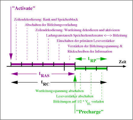
Definition of the timing parameters t RAS , t RP and t RC
The parameter t RAS ( RAS pulse width , Active Command Period , Bank Active Time ) describes the time that must have elapsed after activating a line (or a line in a bank) before a command to deactivate the line ( precharge , Closing the bank) may be sent. The parameter is given by the fact that the amplification of the bit line voltage and the writing back of the information into the cell must be completely completed before the word line can be deactivated. d. H. the smaller the better.
t RP
The parameter “ t RP ” ( “Row Precharge Time” ) describes the minimum time that must have elapsed after a precharge command before a new command to activate a line in the same bank can be sent. This time is defined by the condition that all voltages in the cell field (word line voltage, supply voltage of the sense amplifier) are switched off and the voltages of all lines (especially those of the bit lines) have returned to their starting level.
t RC
The parameter «t RC « ( «Row Cycle Time» ) describes the length of time that must have elapsed between two successive activations of any two rows in the same bank . The value largely corresponds to the sum of the parameters t RAS and t RP and thus describes the minimum time required to refresh a memory line.
DRAM-specific properties
Address multiplex
addressing

The address lines of a DRAM are usually multiplexed , whereas with SRAMs the complete address bus is usually routed to pins for the purpose of higher speed, so that access can take place in a single operation.
Asynchronous DRAMs ( EDO, FPM ) have two input pins RAS ( Row Address Select / Strobe ) and CAS ( Column Address Select / Strobe ) to define the use of the address lines: if there is a falling edge from RAS, the address on the address lines is displayed as Row address interpreted, with a falling edge from CAS it is interpreted as a column address.
RAS
Row Address Strobe , this control signal is present during a valid row address. The memory module stores this address in a buffer.
CAS
Column Address Select or Column Address Strobe , this control signal is present during a valid column address . The memory module stores this address in a buffer.
Synchronous DRAMs ( SDRAM , DDR-SDRAM ) also have the control inputs RAS and CAS , but here they have lost their immediate function. Instead, with synchronous DRAMs, the combination of all control signals ( CKE , RAS , CAS , WE , CS ) are evaluated with a rising clock edge in order to decide whether and in what form the signals on the address lines must be interpreted.
The advantage of saving external address lines is offset by an apparent disadvantage in the form of delayed availability of the column address. However, the column address is only required after the row address has been decoded, a word line has been activated and the bit line signal has been evaluated. However, this internal process requires approx. 15 ns, so that the column address received with a delay does not have a negative effect.
Burst
|
‘Burst Read’ of an asynchronous (EDO) DRAM. The associated column address ( Col ) had to be specified for each burst bit . |
‘Burst Read’ of a synchronous (SDR) DRAM |
|
Cell array of a DRAM with primary sense amplifiers (below) |
A DRAM read amplifier is constructed analogously to the transistors M1, M2, M3 and M4 of such a 6-transistor SRAM cell |


The images on the right show read access in the so-called burst mode for an asynchronous and a synchronous DRAM , as is used with the BEDO DRAM . The characteristic element of a burst access (when reading or writing) is the immediate succession of the data (Data1,…, Data4). The data belong to the same row of the cell field and therefore have the same row address (English row ) but different column addresses (Col1, …, Col4). The time required for the provision of the next data bit within the burst is very short compared to the time required for the provision of the first data bit, measured from the activation of the line.
While all column addresses within the burst had to be specified for asynchronous DRAMs (Col1, …, Col4), only the start address is specified for synchronous DRAMs (SDR, DDR). The column addresses required for the rest of the burst are then generated by an internal counter.
The high data rate within a burst is explained by the fact that the read amplifier only needs to be read (or written) within a burst. The sense amplifiers made up of 2 CMOS inverters (4 transistors) correspond to the basic structure of the cell of a static RAM (see adjacent diagrams). To provide the next burst data bit, only the column address needs to be decoded and the corresponding column selection line activated (this corresponds to the connection lines to the gate connection of the transistors M5 and M6 of an SRAM cell).
Refresh
The refreshment of the memory content , which is necessary at short time intervals , is generally referred to by the English term refresh . The necessity arises from the occurrence of undesired leakage currents which change the amount of charge stored in the capacitors. The leakage currents have an exponential temperature dependency: The time after which the content of a memory cell can no longer be correctly assessed ( retention time ) is halved with a temperature increase of 15 to 20 K. Commercially available DRAMs usually have a prescribed refresh period of 32 ms or 64 ms.
Technically, the primary sense amplifiers in the memory chip (see figure above) are equipped with the function of a latch register. They are designed as SRAM cells, i.e. as flip-flops . When a certain row (English page , Ger. Page ) is selected, the entire line is copied into the latches of the sense amplifier. Since the outputs of the amplifier are also connected to its inputs at the same time, the amplified signals are written back directly into the dynamic memory cells of the selected row and are thus refreshed.
There are different methods of this refresh control:
- RAS-only refresh
- This method is based on the fact that activating a row is automatically linked to an evaluation and writing back of the cell content. For this purpose, the memory controller must externally apply the line address of the line to be refreshed and activate the line via the control signals (see diagram for RAS-only refresh with EDO-DRAM ).
- CAS before RAS refresh
- This refresh method got its name from the control of asynchronous DRAMs, but has also been retained with synchronous DRAMs under the name Auto-Refresh . The naming was based on the otherwise impermissible signal sequence — this type of signal setting is avoided in digital technology because it is relatively error-prone (e.g. during synchronization) — that a falling CAS edge was generated before a falling RAS edge ( see diagram for CBR refresh with EDO-DRAM ). In response to the signal sequence, the DRAM performed a refresh cycle without having to rely on an external address. Instead, the address of the line to be refreshed was provided in an internal counter and automatically increased after the execution.
- Self-refresh
- This method was introduced for special designs of asynchronous DRAMs and was only implemented in a binding manner with synchronous DRAMs. With this method, external control or address signals (for the refresh) are largely dispensed with (see diagram for self-refresh with EDO-DRAM ). The DRAM is in a power-down mode , in which it does not react to external signals (an exception are of course the signals that indicate that it is remaining in the power-saving mode). To obtain the stored information, a DRAM-internal counter is used, which initiates an auto-refresh ( CAS-before-RAS-Refresh ) at predetermined time intervals . In recent DRAMs (DDR-2, DDR-3), the period for the refresh is controlled mostly dependent on the temperature (a so-called T emperature C ontrolled S eleven R efresh, TCSR), in order to reduce the operating current in the self-refresh at low temperatures.
Depending on the circuit environment, normal operation must be interrupted for the refresh; for example, the refresh can be triggered in a regularly called interrupt routine. For example, it can simply read any memory cell in the respective line with its own counting variable and thus refresh this line. On the other hand, there are also situations (especially in video memories) in which the entire memory area is addressed at short intervals anyway, so that no separate refresh operation is required. Some microprocessors , such as the Z80 or the latest processor chipsets , do the refresh fully automatically.
Bank
Before the introduction of synchronous DRAMs, a memory controller had to wait until the information of an activated row was written back and the associated word line was deactivated. Only exactly one line could be activated in the DRAM at a time. Since the length of a complete write or read cycle ( row cycle time, t RC ) was around 80 ns, access to data from different rows was quite time-consuming.
With the introduction of synchronous DRAMs, 2 (16 MiB SDRAM), then 4 (64 MiB SDRAM, DDR-SDRAM), 8 (DDR-3-SDRAM) or even 16 and 32 ( RDRAM ) memory banks were introduced. Memory banks are characterized by the fact that they each have their own address registers and sense amplifiers, so that one row could now be activated per bank . By operating several banks at the same time, you can avoid high latency times, because while one bank is delivering data, the memory controller can already send addresses for another bank.
Prefetch
The significantly lower speed of a DRAM compared to an SRAM is due to the structure and functionality of the DRAM. (Long word lines must be charged, a read cell can only output its charge slowly to the bit line, the read content must be evaluated and written back.) Although these times can generally be shortened using an internally modified structure, the storage density would decrease and so that the space requirement and thus the production price increase.
Instead, a trick is used to increase the external data transfer rate without having to increase the internal speed. In so-called prefetching , the data are read from several column addresses for each addressing and written to a parallel-serial converter ( shift register ). The data is output from this buffer with the higher (external) clock rate. This also explains the data bursts introduced with synchronous DRAMs and in particular their respective minimum burst length (it corresponds precisely to the length of the shift register used as a parallel-to-serial converter and thus the prefetch factor):
- SDR-SDRAM
- Prefetch = 1: 1 data bit per data pin is read out per read request.
- DDR SDRAM
- Prefetch = 2: 2 data bits per data pin are read out per read request and output in a data burst of length 2.
- DDR2 SDRAM
- Prefetch = 4: 4 data bits per data pin are read out per read request and output in a data burst of length 4.
- DDR3 and DDR4 SDRAM
- Prefetch = 8: 8 data bits per data pin are read out per read request and output in a data burst of length 8.
redundancy
As the storage density increases, the probability of defective storage cells increases. So-called redundant elements are provided in the chip design to increase the yield of functional DRAMs . These are additional row and column lines with corresponding memory cells. If defective memory cells are found during the test of the chips, the affected word or row line is deactivated. They are replaced by one (or more) word or row lines from the set of otherwise unused redundant elements (remapping).
The following procedures are used to permanently save this configuration change in the DRAM:
- With the help of a focused laser pulse, appropriately prepared contacts in the decoding circuits of the row or column address are vaporized ( laser fuse ).
- With the help of an electrical overvoltage pulse, electrical contacts are either opened ( e-fuse ) or closed (e.g. by destroying a thin insulating layer) ( anti e-fuse ).
In both cases, these permanent changes are used to program the address of the line to be replaced and the address of the redundant line to be used for it.
The number of redundant elements built into a DRAM design is approximately 1 percent.
The use of redundant elements to correct faulty memory cells must not be confused with active error correction based on parity bits or error-correcting codes (FEC). The error correction described here using redundant elements takes place once before the memory component is delivered to the customer. Subsequent errors (degradation of the component or transmission errors in the system) cannot be eliminated in this way.
See also: Memory module: ECC
Modules

Often entire memory modules are mistaken for the actual memory components . The difference is reflected in the size designation: DIMMs are measured in Mebi or Gibi byte (MiB or GiB), whereas the individual module chip on the DIMM is measured in Mebi or Gibi bit . Advances in manufacturing technology mean that manufacturers can accommodate more and more memory cells on the individual chips, so that 512 MiBit components are readily available. A memory module that complies with the standard is only created by interconnecting individual SDRAM chips.
history
| Year of introduction |
typ. burst rate (ns) |
DRAM type |
|---|---|---|
| 1970 | 00,60 … 300 | classic DRAM |
| 1987 | 00,40 … 50 | FPM-DRAM ( Fast Page Mode DRAM ) |
| 1995 | 00,20 … 30 | EDO-RAM ( Extended Data Output RAM ) |
| 1997 | 000,6… 15 | SDRAM ( Synchronous Dynamic RAM ) |
| 1999 | 00.83 … 1.88 | RDRAM ( Rambus Dynamic RAM ) |
| 2000 | 02.50… 5.00 | DDR-SDRAM (Double Data Rate SDRAM) |
| 2003 | 01.00 … 1.25 | GDDR2-SDRAM |
| 2004 | 00.94 … 2.50 | DDR2 SDRAM |
| 2004 | 00.38 … 0.71 | GDDR3-SDRAM |
| 2006 | 00.44 … 0.50 | GDDR4-SDRAM |
| 2007 | 00.47 … 1.25 | DDR3 SDRAM |
| 2008 | 00.12 … 0.27 | GDDR5-SDRAM |
| 2012 | 00.25 … 0.62 | DDR4 SDRAM |
| 2016 | 00.07 … 0.10 | GDDR5X-SDRAM |
| 2018 | 00.07 | GDDR6-SDRAM |
The first commercially available DRAM chip was the Type 1103 introduced by Intel in 1970 . It contained 1024 memory cells (1 KiBit ). The principle of the DRAM memory cell was developed in 1966 by Robert H. Dennard at the Thomas J. Watson Research Center of IBM .
Since then, the capacity of a DRAM chip has increased by a factor of 8 million and the access time has been reduced to a hundredth. Today (2014) DRAM ICs have capacities of up to 8 GiBit (single die) or 16 GiBit (twin die) and access times of 6 ns. The production of DRAM memory chips is one of the top-selling segments in the semiconductor industry. There is speculation with the products; there is a spot market .
In the beginning, DRAM memories were constructed from individual memory modules (chips) in DIL design. For 16 KiB of working memory (for example in the Atari 600XL or CBM 8032 ) 8 memory modules of type 4116 (16384 cells of 1 bit) or two modules of type 4416 (16384 cells of 4 bit) were required. For 64 KiB 8 blocks of type 4164 ( C64- I) or 2 blocks of type 41464 (C64-II) were needed.
IBM PCs were initially sold at 64 KiB as the minimum memory configuration. Nine building blocks of type 4164 were used here; the ninth block stores the parity bits .
Before the SIMMs came onto the market, there were, for example, motherboards for computers with Intel 80386 processors that could be equipped with 8 MiB of working memory made up of individual chips. For this, 72 individual chips of the type 411000 (1 MiBit) had to be pressed into the sockets. This was a lengthy and error-prone procedure. If the same board was to be equipped with only 4 MiB of RAM, with the considerably cheaper 41256 (256 KiB) chips being used instead of the 411000 type, 144 individual chips had to be inserted: 9 chips make 256 KiB, 16 such groups with 9 chips each resulted in 4 MiB. Larger chips were therefore soldered to form modules that required considerably less space.
application
random access memory
Normally the DRAM in the form of memory modules is used as the main memory of the processor . DRAMs are often classified according to the type of device interface . In the main applications, the interface types Fast Page Mode DRAM (FPM), Extended Data Output RAM (EDO), Synchronous DRAM (SDR), and Double Data Rate Synchronous DRAM (DDR) have developed in chronological order . The properties of these DRAM types are standardized by the JEDEC consortium . In addition, the Rambus DRAM interface exists parallel to SDR / DDR , which is mainly used for memory for servers .
Special applications
Special RAM is used as image and texture memory for graphics cards , for example GDDR3 (Graphics Double Data Rate SDRAM ).
The refreshing of the memory cells can be optimized by restricting them to a special area, so this can be set in the time of the line return in the case of an image memory, for example. It is also u. It can be tolerated if a single pixel temporarily shows the wrong color, so you don’t have to take the worst memory cell on the chip into account. Therefore — despite the same production technologies — significantly faster DRAMs can be produced.
Further types have been developed for special applications: Graphics DRAM (also Synchronous Graphics RAM, SGRAM) is optimized for use on graphics cards , for example, due to its higher data widths , but the basic functionality of a DDR DRAM, for example, is used. The forerunners of graphics RAM were video RAM (VRAM) — a Fast Page Mode RAM optimized for graphics applications with two ports instead of one — and then Window RAM (WRAM), which had EDO features and a dedicated display port .
DRAM types optimized for use in network components have been given the names Network-RAM , Fast-Cycle-RAM and Reduced Latency RAM by various manufacturers . In mobile applications, such as cell phones or PDAs , low energy consumption is important — for this purpose, mobile DRAMs are developed, in which the power consumption is reduced through special circuit technology and manufacturing technology. The pseudo-SRAM (also cellular RAM or 1T-SRAM = 1-transistor-SRAM from other manufacturers ) takes on a hybrid role : the memory itself is a DRAM that behaves like an SRAM to the outside world. This is achieved in that a logic circuit converts the SRAM-typical access mechanism to the DRAM control and the regular refreshing of the memory contents, which is fundamentally necessary for dynamic memories, is carried out by circuits contained in the module.
In the early days of the DRAMs, as these are often still in a ceramic — DIL — housing were built, there were craft solutions, using them as image sensors for DIY cameras. To do this, the metal cover on the ceramic housing was carefully removed, and the die was then directly underneath — without any potting compound. A lens was placed in front of it , which precisely reproduced the image on the die surface. If the chip was completely filled with 1 at the beginning of the exposure , i.e. all storage capacitors were charged, the charges were discharged at different speeds by incident light, depending on the intensity. After a certain (exposure) time, the cells were read out and the image was then interpreted in 1-bit resolution. For grayscale you had to take the same image several times with different exposure times. An additional complication resulted from the fact that the memory cells are not simply arranged according to their binary addresses in order to avoid crosstalk, but these address bits are deliberately “scrambled”. Therefore, after reading out, the image data first had to be brought into the correct arrangement with the inverse pattern. This is hardly possible with today’s chips, as they are usually embedded in plastic potting compound; in addition, digital cameras are now generally accessible and affordable.
Types
There are a variety of types of DRAM that have evolved over time:
- FPM RAM
- EDO RAM
- SDRAM
- DDR SDRAM
- RDRAM
A number of non-volatile RAM ( NVRAM ) technologies are currently under development, such as:
- FeRAM
- MRAM
- PCRAM
The storage capacity is specified in bits and bytes .
RAM used as main memory is often used in the form of memory modules :
- SIMM / PS / 2 SIMM
- DIMM / SO-DIMM
- MicroDIMM
The net total size of RAM modules used as main memory is practically always a power of 2.
literature
- Christof Windeck: Riegel-Reigen: Construction of current memory modules. In: c’t No. 7, 2006, p. 238 ( download of the journal article for a fee )
- Siemens AG (Ed.): Memory Components Data Book. Munich 1994.
- The DRAM story . In: SSCS IEEE SOLID-STATE CIRCUITS SOCIETY NEWS . tape 13 , no. 1 , 2008 ( complete edition as PDF [accessed August 1, 2009]).
Web links
German:
- Christian Hirsch: Compact working memory thanks to Z-RAM . In: heise online . August 15, 2007.
English:
-
Memory 1997 ( PDF , approx. 167 kB ) — Document from Integrated Circuit Engineering Corporation, ISBN 1-877750-59-X (166 kB)
- Section 7. DRAM Technology (PDF, approx. 770 kB) — Chapter 7 of «Memory 1997»
- The evolution of IBM CMOS DRAM Technology — IBM article , July 25, 1994
Individual evidence
- ↑ J. Alex Halderman, Seth D. Schoen, Nadia Heninger, William Clarkson, William Paul, Joseph A. Calandrino, Ariel J. Feldman, Jacob Appelbaum, Edward W. Felten: Lest We Remember: Cold Boot Attacks on Encryption Keys . In: Proc. 2008 USENIX Security Symposium. February 21, 2008, pp. 45-60.
In this article, we are going to learn How to Read File Line by Line in C language.We will read each line from the text file in each iteration.
C fscanf function
The fscanf function is available in the C library. This function is used to read formatted input from a stream. The syntax of fscanf function is:
int fscanf(FILE *stream, const char *format, …)
Parameters
- stream − This is the pointer to a FILE object that identifies the stream.
- format − This is the C string that contains one or more of the following items − Whitespace character, Non-whitespace character, and Format specifiers. A format specifier will be as [=%[*][width][modifiers]type=].
1. How to Read File Line by Line in C
Here we are making use of the fscanf function to read the text file.The first thing we are going to do is open the file in reading mode. So using fopen() function and “r” read mode we opened the file.The next step is to find the file stats like what is the size of the data this file contains. so we can allocate exact memory for the buffer that is going to hold the content of this file. We are using the stat() function to find the file size.
- Once we have the size and buffer allocated for this size, we start reading the file by using the fscanf() function.
- We keep reading the file line by line until we reach the end of the file. In fscanf function, we are passing n as the argument so we can read the text until we find a next line character.
- The code will look like this: “fscanf(in_file, “%[^n]”
C program to Read File Line by Line
To run this program, we need one text file with the name Readme.txt in the same folder where we have our code.The content of the file is:
Hello My name is
John
danny
#include <stdio.h>
#include <stdlib.h>
#include <sys/stat.h>

const char* filename = "Readme.txt";

int main(int argc, char *argv[])
{
    FILE *in_file = fopen(filename, "r");
    if (!in_file)
	{
        perror("fopen");
        return 0;
    }

    struct stat sb;
    if (stat(filename, &sb) == -1) {
        perror("stat");
        return 0;
    }

    char *textRead = malloc(sb.st_size);
	int i = 1;

    while (fscanf(in_file, "%[^n] ", textRead) != EOF)
	{
        printf("Line %d is  %sn",i, textRead);
		i++;
    }

    fclose(in_file);
    return 0;
}
Output
Line 1 is  Hello My name is
Line 2 is  John
Line 3 is  danny
Hi, I am new in VBScript. i used a VBScript for reading MSWord file word by word. here is the code of my Script.
Option Explicit


Dim objWord

Dim wordPath

Dim currentDocument

Dim numberOfWords
Dim i
Dim objDialog
Set objDialog = CreateObject("UserAccounts.CommonDialog")
objDialog.Filter = "VBScript Scripts|*.vbs|All Files|*.*"
objDialog.FilterIndex = 1
objDialog.InitialDir = "C:"
intResult = objDialog.ShowOpen
If intResult = 0 Then
    Wscript.Quit
Else
    Wscript.Echo objDialog.FileName
End If

wordPath = "C:Documents and SettingssapuserDesktopharry.doc"
WScript.Echo "Extract Data from " & wordPath

Set objWord = CreateObject("Word.Application")


objWord.DisplayAlerts = 0


objWord.Documents.Open wordPath, false, true

Set currentDocument = objWord.Documents(1)

NumberOfWords = currentDocument.words.count
WScript.Echo "There are " & NumberOfWords & " words " & vbCRLF
For i = 1 to NumberOfWords
	WScript.Echo currentDocument.words(i)
Next

currentDocument.Close

Set currentDocument = Nothing

objWord.Quit
Set objWord = Nothing
In this line we count the total number of words in my doc files
NumberOfWords = currentDocument.words.count
and this for loop display the contents of my doc file word by word
For i = 1 to NumberOfWords<br />
	WScript.Echo currentDocument.words(i)<br />
Next<br />
But I want to read my doc file line by line. Is there any function which gets a line rather than a word?
Please suggest me a way to get a line by line display of my doc.
Thanks.
Updated 18-Oct-11 23:37pm
Try using Paragraphs
For Each p In currentDocument.Paragraphs
    WScript.Echo p.Range.Text
Next p
This content, along with any associated source code and files, is licensed under The Code Project Open License (CPOL)
CodeProject,
20 Bay Street, 11th Floor Toronto, Ontario, Canada M5J 2N8
+1 (416) 849-8900
Magnetic-core memory was the predominant form of random-access computer memory for 20 years between about 1955 and 1975.
Such memory is often just called core memory, or, informally, core.

A 32 x 32 core memory plane storing 1024 bits (or 128 bytes) of data. The small black rings at the intersections of the grid wires, organised in four squares, are the ferrite cores.
Core memory uses toroids (rings) of a hard magnetic material (usually a semi-hard ferrite) as transformer cores, where each wire threaded through the core serves as a transformer winding. Two or more wires pass through each core. Magnetic hysteresis allows each of the cores to «remember», or store a state.
Each core stores one bit of information. A core can be magnetized in either the clockwise or counter-clockwise direction. The value of the bit stored in a core is zero or one according to the direction of that core’s magnetization. Electric current pulses in some of the wires through a core allow the direction of the magnetization in that core to be set in either direction, thus storing a one or a zero. Another wire through each core, the sense wire, is used to detect whether the core changed state.
The process of reading the core causes the core to be reset to a zero, thus erasing it. This is called destructive readout. When not being read or written, the cores maintain the last value they had, even if the power is turned off. Therefore, they are a type of non-volatile memory.
Using smaller cores and wires, the memory density of core slowly increased, and by the late 1960s a density of about 32 kilobits per cubic foot (about 0.9 kilobits per litre) was typical. However, reaching this density required extremely careful manufacture, which was almost always carried out by hand in spite of repeated major efforts to automate the process. The cost declined over this period from about $1 per bit to about 1 cent per bit. The introduction of the first semiconductor memory chips in the late 1960s, which initially created static random-access memory (SRAM), began to erode the market for core memory. The first successful dynamic random-access memory (DRAM), the Intel 1103, followed in 1970. Its availability in quantity at 1 cent per bit marked the beginning of the end for core memory.[1]
Improvements in semiconductor manufacturing led to rapid increases in storage capacity and decreases in price per kilobyte, while the costs and specs of core memory changed little. Core memory was driven from the market gradually between 1973 and 1978.
Depending on how it was wired, core memory could be exceptionally reliable. Read-only core rope memory, for example, was used on the mission-critical Apollo Guidance Computer essential to NASA’s successful Moon landings.
Although core memory is obsolete, computer memory is still sometimes called «core» even though it is made of semiconductors, particularly by people who had worked with machines having actual core memory. The files that result from saving the entire contents of memory to disk for inspection, which is nowadays commonly performed automatically when a major error occurs in a computer program, are still called «core dumps».
HistoryEdit
DevelopersEdit
The basic concept of using the square hysteresis loop of certain magnetic materials as a storage or switching device was known from the earliest days of computer development. Much of this knowledge had developed due to an understanding of transformers, which allowed amplification and switch-like performance when built using certain materials. The stable switching behavior was well known in the electrical engineering field, and its application in computer systems was immediate. For example, J. Presper Eckert and Jeffrey Chuan Chu had done some development work on the concept in 1945 at the Moore School during the ENIAC efforts.[2]
Robotics pioneer George Devol filed a patent[3] for the first static (non-moving) magnetic memory on 3 April 1946. Devol’s magnetic memory was further refined via 5 additional patents[4][5][6][7][8] and ultimately used in the first Industrial Robot. Frederick Viehe applied for various patents on the use of transformers for building digital logic circuits in place of relay logic beginning in 1947. A fully developed core system was patented in 1947, and later purchased by IBM in 1956.[9] This development was little-known, however, and the mainstream development of core is normally associated with three independent teams.
Substantial work in the field was carried out by the Shanghai-born American physicists An Wang and Way-Dong Woo, who created the pulse transfer controlling device in 1949.[10][11] The name referred to the way that the magnetic field of the cores could be used to control the switching of current; his patent focused on using cores to create delay-line or shift-register memory systems. Wang and Woo were working at Harvard University’s Computation Laboratory at the time, and the university was not interested in promoting inventions created in their labs. Wang was able to patent the system on his own.
The MIT Project Whirlwind computer required a fast memory system for real-time aircraft tracking. At first, an array of Williams tubes—a storage system based on cathode ray tubes—was used, but proved temperamental and unreliable. Several researchers in the late 1940s conceived the idea of using magnetic cores for computer memory, but MIT computer engineer Jay Forrester received the principal patent for his invention of the coincident-current core memory that enabled the 3D storage of information.[12][13] William Papian of Project Whirlwind cited one of these efforts, Harvard’s «Static Magnetic Delay Line», in an internal memo. The first core memory of 32 × 32 × 16 bits was installed on Whirlwind in the summer of 1953. Papian stated: «Magnetic-Core Storage has two big advantages: (1) greater reliability with a consequent reduction in maintenance time devoted to storage; (2) shorter access time (core access time is 9 microseconds: tube access time is approximately 25 microseconds) thus increasing the speed of computer operation.»[14]
In April 2011, Forrester recalled, «the Wang use of cores did not have any influence on my development of random-access memory. The Wang memory was expensive and complicated. As I recall, which may not be entirely correct, it used two cores per binary bit and was essentially a delay line that moved a bit forward. To the extent that I may have focused on it, the approach was not suitable for our purposes.» He describes the invention and associated events, in 1975.[15] Forrester has since observed, «It took us about seven years to convince the industry that random-access magnetic-core memory was the solution to a missing link in computer technology. Then we spent the following seven years in the patent courts convincing them that they had not all thought of it first.»[16]
A third developer involved in the early development of core was Jan A. Rajchman at RCA. A prolific inventor, Rajchman designed a unique core system using ferrite bands wrapped around thin metal tubes,[17] building his first examples using a converted aspirin press in 1949.[9] Rajchman later developed versions of the Williams tube and led development of the Selectron.[18]
Two key inventions led to the development of magnetic core memory in 1951. The first, An Wang’s, was the write-after-read cycle, which solved the problem of how to use a storage medium in which the act of reading erased the data read, enabling the construction of a serial, one-dimensional shift register (of 50 bits), using two cores to store a bit. A Wang core shift register is in the Revolution exhibit at the Computer History Museum. The second, Forrester’s, was the coincident-current system, which enabled a small number of wires to control a large number of cores enabling 3D memory arrays of several million bits. The first use of core was in the Whirlwind computer, and Project Whirlwind’s «most famous contribution was the random-access, magnetic core storage feature.»[19] Commercialization followed quickly. Magnetic core was used in peripherals of the ENIAC in 1953,[20] the IBM 702[21] delivered in July 1955, and later in the 702 itself. The IBM 704 (1954) and the Ferranti Mercury (1957) used magnetic-core memory.
It was during the early 1950s that Seeburg Corporation developed one of the first commercial applications of coincident-current core memory storage in the «Tormat» memory of its new range of jukeboxes, starting with the V200 developed in 1953 and released in 1955.[22] Numerous uses in computing, telephony and industrial process control followed.
Patent disputesEdit
Wang’s patent was not granted until 1955, and by that time magnetic-core memory was already in use. This started a long series of lawsuits, which eventually ended when IBM bought the patent outright from Wang for US$500,000.[23] Wang used the funds to greatly expand Wang Laboratories, which he had co-founded with Dr. Ge-Yao Chu, a schoolmate from China.
MIT wanted to charge IBM $0.02 per bit royalty on core memory. In 1964, after years of legal wrangling, IBM paid MIT $13 million for rights to Forrester’s patent—the largest patent settlement to that date.[24][25]
Production economicsEdit
In 1953, tested but not-yet-strung cores cost US$0.33 each. As manufacturing volume increased, by 1970 IBM was producing 20 billion cores per year, and the price per core fell to US$0.0003. Core sizes shrank over the same period from around 0.1 inches (2.5 mm) diameter in the 1950s to 0.013 inches (0.33 mm) in 1966.[26] The power required to flip the magnetization of one core is proportional to the volume, so this represents a drop in power consumption by a factor of 125.
The cost of complete core memory systems was dominated by the cost of stringing the wires through the cores. Forrester’s coincident-current system required one of the wires to be run at 45 degrees to the cores, which proved difficult to wire by machine, so that core arrays had to be assembled under microscopes by workers with fine motor control.
In 1956, a group at IBM filed for a patent on a machine to automatically thread the first few wires through each core. This machine held the full plane of cores in a «nest» and then pushed an array of hollow needles through the cores to guide the wires.[27] Use of this machine reduced the time taken to thread the straight X and Y select lines from 25 hours to 12 minutes on a 128 by 128 core array.[28]
Smaller cores made the use of hollow needles impractical, but there were numerous advances in semi-automatic core threading. Support nests with guide channels were developed. Cores were permanently bonded to a backing sheet «patch» that supported them during manufacture and later use. Threading needles were butt welded to the wires, so the needle and wire diameters were the same, and efforts were made to entirely eliminate the use of needles.[29][30]
The most important change, from the point of view of automation, was the combination of the sense and inhibit wires, eliminating the need for a circuitous diagonal sense wire. With small changes in layout, this also allowed much tighter packing of the cores in each patch.[31][32]
By the early 1960s, the cost of core fell to the point that it became nearly universal as main memory, replacing both inexpensive low-performance drum memory and costly high-performance systems using vacuum tubes, and later discrete transistors as memory. The cost of core memory declined sharply over the lifetime of the technology: costs began at roughly US$1.00 per bit and dropped to roughly US$0.01 per bit. Core was replaced with integrated semiconductor RAM chips in the 1970s.
An example of the scale, economics, and technology of core memory in the 1960s was the 256K 36-bit word (1.2 MiB[33]) core memory unit installed on the PDP-6 at the MIT Artificial Intelligence Laboratory by 1967.[34] This was considered «unimaginably huge» at the time, and nicknamed the «Moby Memory».[35] It cost $380,000 ($0.04/bit) and was 69 inches wide, 50 inches tall, and 25 inches deep with its supporting circuitry (189 kilobits/cubic foot = 6.7 kilobits/litre). Its cycle time was 2.75 μs.[36][37][38]
DescriptionEdit
Diagram of a 4×4 plane of magnetic core memory in an X/Y line coincident-current setup. X and Y are drive lines, S is sense, Z is inhibit. Arrows indicate the direction of current for writing.
Close-up of a core plane. The distance between the rings is roughly 1 mm (0.04 in). The green horizontal wires are X; the Y wires are dull brown and vertical, toward the back. The sense wires are diagonal, colored orange, and the inhibit wires are vertical twisted pairs.
The term «core» comes from conventional transformers whose windings surround a magnetic core. In core memory, the wires pass once through any given core—they are single-turn devices. The properties of materials used for memory cores are dramatically different from those used in power transformers. The magnetic material for a core memory requires a high degree of magnetic remanence, the ability to stay highly magnetized, and a low coercivity so that less energy is required to change the magnetization direction. The core can take two states, encoding one bit. The core memory contents are retained even when the memory system is powered down (non-volatile memory). However, when the core is read, it is reset to a «zero» value. Circuits in the computer memory system then restore the information in an immediate re-write cycle.
How core memory worksEdit
One of three inter-connected modules that make up an Omnibus-based (PDP 8/e/f/m) PDP-8 core memory plane.
One of three inter-connected modules that make up an Omnibus-based PDP-8 core memory plane. This is the middle of the three and contains the array of actual ferrite cores.
One of three inter-connected modules that make up an Omnibus-based PDP-8 core memory plane.
The most common form of core memory, X/Y line coincident-current, used for the main memory of a computer, consists of a large number of small toroidal ferrimagnetic ceramic ferrites (cores) held together in a grid structure (organized as a «stack» of layers called planes), with wires woven through the holes in the cores’ centers. In early systems there were four wires: X, Y, Sense, and Inhibit, but later cores combined the latter two wires into one Sense/Inhibit line.[31] Each toroid stored one bit (0 or 1). One bit in each plane could be accessed in one cycle, so each machine word in an array of words was spread over a «stack» of planes. Each plane would manipulate one bit of a word in parallel, allowing the full word to be read or written in one cycle.
Core relies on the «square loop» properties of the ferrite material used to make the toroids. An electric current in a wire that passes through a core creates a magnetic field. Only a magnetic field greater than a certain intensity («select») can cause the core to change its magnetic polarity. To select a memory location, one of the X and one of the Y lines are driven with half the current («half-select») required to cause this change. Only the combined magnetic field generated where the X and Y lines cross (a logical AND function) is sufficient to change the state; other cores will see only half the needed field («half-selected»), or none at all. By driving the current through the wires in a particular direction, the resulting induced field forces the selected core’s magnetic flux to circulate in one direction or the other (clockwise or counterclockwise). One direction is a stored 1, while the other is a stored 0.
The toroidal shape of a core is preferred since the magnetic path is closed, there are no magnetic poles and thus very little external flux. This allows the cores to be packed closely together without allowing their magnetic fields to interact. The alternating 45-degree positioning used in early core arrays was necessitated by the diagonal sense wires. With the elimination of these diagonal wires, tighter packing was possible.[32]
Reading and writingEdit
Diagram of the hysteresis curve for a magnetic memory core during a read operation. Sense line current pulse is high («1») or low («0») depending on original magnetization state of the core.
To read a bit of core memory, the circuitry tries to flip the bit to the polarity assigned to the 0 state, by driving the selected X and Y lines that intersect at that core.
- If the bit was already 0, the physical state of the core is unaffected.
- If the bit was previously 1, then the core changes magnetic polarity. This change, after a delay, induces a voltage pulse into the Sense line.
The detection of such a pulse means that the bit had most recently contained a 1. Absence of the pulse means that the bit had contained a 0. The delay in sensing the voltage pulse is called the access time of the core memory.
Following any such read, the bit contains a 0. This illustrates why a core memory access is called a destructive read: Any operation that reads the contents of a core erases those contents, and they must immediately be recreated.
To write a bit of core memory, the circuitry assumes there has been a read operation and the bit is in the 0 state.
- To write a 1 bit, the selected X and Y lines are driven, with current in the opposite direction as for the read operation. As with the read, the core at the intersection of the X and Y lines changes magnetic polarity.
- To write a 0 bit, two methods can be applied. The first one is the same as reading process with current in the original direction. The second has reversed logic. Write 0 bit, in other words, is to inhibit the writing of a 1 bit. The same amount of current is also sent through the Inhibit line. This reduces the net current flowing through the respective core to half the select current, inhibiting change of polarity.
The access time plus the time to rewrite is the memory cycle time.
The Sense wire is used only during the read, and the Inhibit wire is used only during the write. For this reason, later core systems combined the two into a single wire, and used circuitry in the memory controller to switch the function of the wire. However, when Sense wire crosses too many cores, the half select current can also induce a considerable voltage across the whole line due to the superposition of the voltage at each single core. This potential risk of «misread» limits the minimum number of the Sense wire. Increasing Sense wires requires more decode circuits.
Core memory controllers were designed so that every read was followed immediately by a write (because the read forced all bits to 0, and because the write assumed this had happened). Computers began to take advantage of this fact. For example, a value in memory could be read and incremented (as for example by the AOS instruction on the PDP-6) almost as quickly as it could be read; the hardware simply incremented the value between the read phase and the write phase of a single memory cycle (perhaps signalling the memory controller to pause briefly in the middle of the cycle). This might be twice as fast as the process of obtaining the value with a read-write cycle, incrementing the value in some processor register, and then writing the new value with another read-write cycle.
Other forms of core memoryEdit
A 10.8×10.8 cm plane of magnetic core memory with 64 x 64 bits (4 Kb), as used in a CDC 6600. Inset shows word line architecture with two wires per bit
Word line core memory was often used to provide register memory. Other names for this type are linear select and 2-D. This form of core memory typically wove three wires through each core on the plane, word read, word write, and bit sense/write. To read or clear words, the full current is applied to one or more word read lines; this clears the selected cores and any that flip induce voltage pulses in their bit sense/write lines. For read, normally only one word read line would be selected; but for clear, multiple word read lines could be selected while the bit sense/write lines ignored. To write words, the half current is applied to one or more word write lines, and half current is applied to each bit sense/write line for a bit to be set. In some designs, the word read and word write lines were combined into a single wire, resulting in a memory array with just two wires per bit. For write, multiple word write lines could be selected. This offered a performance advantage over X/Y line coincident-current in that multiple words could be cleared or written with the same value in a single cycle. A typical machine’s register set usually used only one small plane of this form of core memory. Some very large memories were built with this technology, for example the Extended Core Storage (ECS) auxiliary memory in the CDC 6600, which was up to 2 million 60-bit words.
Another form of core memory called core rope memory provided read-only storage. In this case, the cores, which had more linear magnetic materials, were simply used as transformers; no information was actually stored magnetically within the individual cores. Each bit of the word had one core. Reading the contents of a given memory address generated a pulse of current in a wire corresponding to that address. Each address wire was threaded either through a core to signify a binary [1], or around the outside of that core, to signify a binary [0]. As expected, the cores were much larger physically than those of read-write core memory. This type of memory was exceptionally reliable. An example was the Apollo Guidance Computer used for the NASA Moon landings.
Physical characteristicsEdit
The performance of early core memories can be characterized in today’s terms as being very roughly comparable to a clock rate of 1 MHz (equivalent to early 1980s home computers, like the Apple II and Commodore 64). Early core memory systems had cycle times of about 6 µs, which had fallen to 1.2 µs by the early 1970s, and by the mid-70s it was down to 600 ns (0.6 µs). Some designs had substantially higher performance: the CDC 6600 had a memory cycle time of 1.0 µs in 1964, using cores that required a half-select current of 200 mA.[39] Everything possible was done in order to decrease access times and increase data rates (bandwidth), including the simultaneous use of multiple grids of core, each storing one bit of a data word. For instance, a machine might use 32 grids of core with a single bit of the 32-bit word in each one, and the controller could access the entire 32-bit word in a single read/write cycle.
Core memory is non-volatile storage—it can retain its contents indefinitely without power. It is also relatively unaffected by EMP and radiation. These were important advantages for some applications like first-generation industrial programmable controllers, military installations and vehicles like fighter aircraft, as well as spacecraft, and led to core being used for a number of years after availability of semiconductor MOS memory (see also MOSFET). For example, the Space Shuttle IBM AP-101B flight computers used core memory, which preserved the contents of memory even through the Challenger‘s disintegration and subsequent plunge into the sea in 1986.[40] Another characteristic of early core was that the coercive force was very temperature-sensitive; the proper half-select current at one temperature is not the proper half-select current at another temperature. So a memory controller would include a temperature sensor (typically a thermistor) to adjust the current levels correctly for temperature changes. An example of this is the core memory used by Digital Equipment Corporation for their PDP-1 computer; this strategy continued through all of the follow-on core memory systems built by DEC for their PDP line of air-cooled computers. Another method of handling the temperature sensitivity was to enclose the magnetic core «stack» in a temperature controlled oven. Examples of this are the heated-air core memory of the IBM 1620 (which could take up to 30 minutes to reach operating temperature, about 106 °F (41 °C) and the heated-oil-bath core memory of the IBM 7090, early IBM 7094s, and IBM 7030.
Core was heated instead of cooled because the primary requirement was a consistent temperature, and it was easier (and cheaper) to maintain a constant temperature well above room temperature than one at or below it.
In 1980, the price of a 16 kW (kiloword, equivalent to 32 kB) core memory board that fitted into a DEC Q-bus computer was around US$3,000. At that time, core array and supporting electronics fit on a single printed circuit board about 25 × 20 cm in size, the core array was mounted a few mm above the PCB and was protected with a metal or plastic plate.
Diagnosing hardware problems in core memory required time-consuming diagnostic programs to be run. While a quick test checked if every bit could contain a one and a zero, these diagnostics tested the core memory with worst-case patterns and had to run for several hours. As most computers had just a single core memory board, these diagnostics also moved themselves around in memory, making it possible to test every bit. An advanced test was called a «Shmoo test» in which the half-select currents were modified along with the time at which the sense line was tested («strobed»). The data plot of this test seemed to resemble a cartoon character called «Shmoo,» and the name stuck. In many occasions, errors could be resolved by gently tapping the printed circuit board with the core array on a table. This slightly changed the positions of the cores along the wires running through them, and could fix the problem. The procedure was seldom needed, as core memory proved to be very reliable compared to other computer components of the day.
-
This microSDHC card holds 8 billion bytes (8 GB). It rests on a section of magnetic-core memory that uses 64 cores to hold eight bytes. The microSDHC card holds over one billion times more bytes in much less physical space.
-
Magnetic-core memory, 18×24 bits, with a US quarter for scale
-
Magnetic-core memory close-up
See alsoEdit
- Bubble memory
- Core dump
- Core rope memory
- Delay-line memory
- Electronic calculators
- Ferroelectric RAM
- Magnetoresistive random-access memory
- Read-mostly memory (RMM)
- Thin-film memory
- Twistor memory
ReferencesEdit
- ^ Bellis, Mary (23 February 2018). «Who Invented the Intel 1103 DRAM Chip?». Thought Co. US.
- ^ Eckert, J. Presper (October 1953). «A Survey of Digital Computer Memory Systems». Proceedings of the IRE. US: IEEE. 41 (10): 1393–1406. doi:10.1109/JRPROC.1953.274316. ISSN 0096-8390. S2CID 8564797.
- ^ «Magnetic Process Control No. 2590091» (PDF). Georgedevol.com. 25 March 1952. Retrieved 15 November 2021.
- ^ «Magnetic Storage ands Sensing Device No. 2741757» (PDF). Georgedevol.com. 25 March 1952. Retrieved 15 November 2021.
- ^ «Sensing Device for Magnetic Record No. 2926844» (PDF). Georgedevol.com. 25 March 1952. Retrieved 15 November 2021.
- ^ «Magnetic Storage Devices No. 3035253» (PDF). Georgedevol.com. 25 March 1952. Retrieved 15 November 2021.
- ^ «Coincidence Detectors No. 3016465» (PDF). Georgedevol.com. 25 March 1952. Retrieved 15 November 2021.
- ^ «Ferroresonant Devices No. 3246219» (PDF). Georgedevol.com. 25 March 1952. Retrieved 15 November 2021.
- ^ a b Reilly, Edwin D. (2003). Milestones in computer science and information technology. Westport, CT: Greenwood Press. p. 164. ISBN 1-57356-521-0.
- ^ «Wang Interview, An Wang’s Early Work in Core Memories». Datamation. US: Technical Publishing Company: 161–163. March 1976.
- ^ US 2708722, Wang, An, «Pulse Transfer Controlling Device», issued 17 May 2020.
- ^ Forrester, Jay W. (1951). «Digital Information In Three Dimensions Using Magnetic Cores». Journal of Applied Physics. 22 (22). doi:10.1063/1.1699817.
- ^ US 2736880, Forrester, Jay W., «Multicoordinate digital information storage device», issued 28 February 1956
- ^ «Whirlwind» (PDF). The Computer Museum Report. Massachusetts: The Computer Museum: 13. Winter 1983 – via Microsoft.
- ^ Evans, Christopher (July 1983). «Jay W. Forrester Interview». Annals of the History of Computing. 5 (3): 297–301. doi:10.1109/mahc.1983.10081. S2CID 25146240.
- ^ Kleiner, Art (4 February 2009). «Jay Forrester’s Shock to the System». The MIT Sloan Review. US. Retrieved 1 April 2018.
- ^ Jan A. Rajchman, Magnetic System, U.S. Patent 2,792,563, granted 14 May 1957.
- ^ Hittinger, William (1992). «Jan A. Rajchman». Memorial Tributes. US: National Academy of Engineering. 5: 229.
- ^ Redmond, Kent C.; Smith, Thomas M. (1980). Project Whirlwind — The History of a Pioneer Computer. Bedford, Mass.: Digital Press. p. 215. ISBN 0932376096.
- ^ Auerbach, Isaac L. (2 May 1952). «A static magnetic memory system for the ENIAC». Proceedings of the 1952 ACM national meeting (Pittsburgh) on — ACM ’52. pp. 213–222. doi:10.1145/609784.609813. ISBN 9781450373623. S2CID 17518946.
- ^ Pugh, Emerson W.; Johnson, Lyle R.; Palmer, John H. (1991). IBM’s 360 and Early 370 Systems. MIT Press. p. 32. ISBN 978-0-262-51720-1.
- ^ Clarence Schultz and George Boesen, Selectors for Automatic Phonographs, U.S. Patent 2,792,563, granted Feb. 2, 1960.
- ^ «An Wang Sells Core Memory Patent to IBM». US: Computer History Museum. Retrieved 12 April 2010.
- ^ «Magnetic Core Memory». CHM Revolution. Computer History Museum. Retrieved 1 April 2018.
- ^ Pugh, Johnson & Palmer 1991, p. 182
- ^ Pugh, Johnson & Palmer 1991, pp. 204–6
- ^ Walter P. Shaw and Roderick W. Link, Method and Apparatus for Threading Perforated Articles, U.S. Patent 2,958,126, granted Nov. 1, 1960.
- ^ Bashe, Charles J.; Johnson, Lyle R.; Palmer, John H. (1986). IBM’s Early Computers. Cambridge, MA: MIT Press. p. 268. ISBN 0-262-52393-0.
- ^ Robert L. Judge, Wire Threading Method and Apparatus, U.S. Patent 3,314,131, granted Apr. 18, 1967.
- ^ Ronald A. Beck and Dennis L. Breu, Core Patch Stringing Method, U.S. Patent 3,872,581, granted Mar. 25, 1975.
- ^ a b Creighton D. Barnes, et al., Magnetic core storage device having a single winding for both the sensing and inhibit function, U.S. Patent 3,329,940, granted 4 July 1967.
- ^ a b Victor L. Sell and Syed Alvi, High Density Core Memory Matrix, U.S. Patent 3,711,839, granted Jan. 16, 1973.
- ^ Internally, the Moby Memory had 40 bits per word, but they were not exposed to the PDP-10 processor.
- ^ Project MAC. Progress Report IV. July 1966-July 1967 (PDF) (Report). Massachusetts Institute of Technology. p. 18. 681342. Archived from the original (PDF) on 8 May 2021. Retrieved 7 December 2020.
- ^ Eric S. Raymond, Guy L. Steele, The New Hacker’s Dictionary, 3rd edition, 1996, ISBN 0262680920, based on the Jargon File, s.v. ‘moby’, p. 307
- ^ «FABRI-TEK Mass Core ‘Moby’ Memory». Computer History Museum. US. 102731715. Retrieved 7 December 2020.
- ^ Krakauer, Lawrence J. «Moby Memory». Retrieved 7 December 2020.
- ^ Steven Levy, Hackers: Heroes of the Computer Revolution, 2010 (25th anniversary edition), ISBN 1449393748, p. 98
- ^ «Section 4». Control Data 6600 Training Manual. Control Data Corporation. June 1965. Document number 60147400.
- ^ «Magnetic Core Memory». US: National High Magnetic Field Laboratory: Museum of Electricity and Magnetism. Archived from the original on 10 June 2010.
External linksEdit
Look up core memory in Wiktionary, the free dictionary.
- Interactive Java Tutorial — Magnetic Core Memory National High Magnetic Field Laboratory
- Core Memory at Columbia University
- «Magnetic Cores». Digital Computer Basics (Rate Training Manual). Naval Education and Training Command. 1978. pp. 95–. NAVEDTRA 10088-B.
- Core Memory on the PDP-11
- Core memory and other early memory types accessed 15 April 2006
- Coincident Current Ferrite Core Memories Byte magazine, July 1976
- Casio AL-1000 calculator – Shows close-ups of the magnetic core memory in this desktop electronic calculator from the mid-1960s.
- Still used core memory in multiple devices in a German computer museum
- Werner, G.E.; Whalen, R.M.; Lockhart, N.F.; Flaker, R.C. (March 1967). «A 110-Nanosecond Ferrite Core Memory» (PDF). IBM Journal of Research and Development. 11 (2): 153–161. doi:10.1147/rd.112.0153. Archived from the original (PDF) on 26 February 2009.
- Background on core memory for computers
13 May 2017
It’s easy to eat a lot of memory when parsing text in Node, especially when
reading from a stream.
Suppose you’re reading data from the DARPA Intrusion Detection Data
Sets, and you want to compute the mean time of an attack. Assume you’ve
already processed the data so it’s just a list of timestamps as hours, minutes,
and seconds.
10:09:57
02:13:20
00:03:36
10:21:33
19:37:32
Here’s JavaScript that parses each timestamp to get the total number of seconds
and a count of the number of timestamps.
let total = 0;
let count = 0;

const parse = (timestamp) => {
  const [h, m, s] = timestamp.split(':');
  total += (Number(h) || 0) * 60 * 60;
  total += (Number(m) || 0) * 60;
  total += (Number(s) || 0);
  count += 1;
};
With that, you can compute the mean as Math.ceil(total / count). If you’re
reading timestamps from process.stdin in Node, you can store them in
a string and compute the mean once you’ve seen them all.
let text = '';

process.stdin.setEncoding('utf-8');

process.stdin.on('data', (data) => {
  if (data) {
    text += data;
  }
});

process.stdin.on('end', () => {
  const timestamps = text.split("n");
  timestamps.forEach(parse);

  const mean = Math.ceil(total / count);
  console.log(`${mean} seconds`);
});
The gotcha is that all that text is kept in memory. Node has a maximum String
size, and it’ll throw exceptions if you try and read too much data. Running on
an old iMac, I can read about 512 MB before Node crashes.
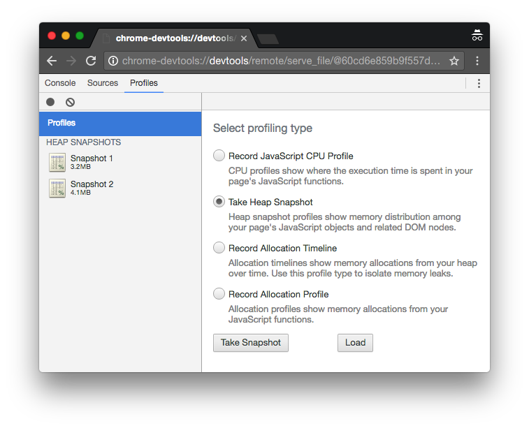
To figure out how much memory this used, I ran the code above through Chrome
DevTools on a 34 MB input file and captured two heap snapshots.
$ du -h data.txt
 34M    data.txt

$ node --inspect --debug-brk mean-time.js < data.txt
To start debugging, open the following URL in Chrome:
    chrome-devtools://devtools/remote/serve_file/...
Debugger attached.
Waiting for the debugger to disconnect...

The first snapshot is the amount of memory used on startup, before any data has
been processed. It’s 3.2 MB. The second snapshot is the amount of memory used
after all the data has been processed. It’s 38.3 MB.
Which means most of the memory is being used to store all that text.
Fortunately, there’s an easy workaround. Check for complete timestamps as each
new chunk of data comes in and parse each one on the fly.
let text = '';

process.stdin.setEncoding('utf-8');

process.stdin.on('data', (data) => {
  if (data) {
    text += data;

    const timestamps = text.split("n");
    if (timestamps.length > 1) {
      text = timestamps.splice(-1, 1)[0];
      timestamps.forEach(parse);
    }
  }
});

process.stdin.on('end', () => {
  parse(text);

  const mean = Math.ceil(total / count);
  console.log(`${mean} seconds`);
});
This code splits the buffered text on newlines as it arrives. It parses
every timestamp but the last, which is used to start the next buffer. At the
end, it parses anything remaining. Saving that the last timestamp until the end
means that if we get a partial timestamp, like 02:13:, we won’t try to parse
it until we see the whole thing.
I ran the same experiment to see if memory use improved.
$ node --inspect --debug-brk mean-time.js < data.txt
To start debugging, open the following URL in Chrome:
    chrome-devtools://devtools/remote/serve_file/...
Debugger attached.
Waiting for the debugger to disconnect...
As before, the first snapshot is the amount of memory used on startup, before
any data has been processed. It’s still 3.2 MB. The second snapshot is the
amount of memory used after all the data has been processed. This time it’s only
4.1 MB. That’s 34.2 MB of memory saved!
By processing data as it becomes available, you can read data line-by-line and
keep memory use low.
PRIORITY CLAIM
This application claims priority from European patent application No. 02425084.7, filed Feb. 20, 2002, which is incorporated herein by reference.
TECHNICAL FIELD
The present invention relates generally to the field of semiconductor memories, particularly non-volatile memories. More particularly, the invention relates to electrically erasable and programmable non-volatile memories, such as flash memories.
BACKGROUND OF THE INVENTION
As known, data is written (programmed) to a flash memory by means of hot-electron injection into floating-gate electrodes (hereinafter, floating gates) of the memory cells. To erase the data, electrons are extracted from the floating gates of the memory cells by means of the mechanism known as Fowler-Nordheim tunnelling at high electric fields, giving rise to a Fowler-Nordheim current.
In conventional flash memories, the erase operation has a global character, affecting the whole array (also called matrix) of memory cells or, where memory sectors are provided with, a whole memory sector. All the memory cells of the matrix or memory sector to be erased are submitted to an erase voltage
VGB=VG−VB
where VG is, for example, a negative voltage (e.g., ranging from −8V to −9V) applied simultaneously to all the word lines of the matrix or memory sector, that is, to the memory cells’ control-gate electrode (hereinafter, control gate), and VB is a positive voltage (e.g., ranging from 8V to 9V) applied to the common substrate or bulk electrode of the memory cells of the matrix or memory sector, that is, the (typically P-type) doped semiconductor well in which the memory cells of the matrix or memory sector are formed. Starting from a prescribed initial value, the erase voltage VGB is progressively increased (in absolute value) until, by progressive extraction of electrons from the memory cells’ floating gates, the threshold voltage of all the memory cells is brought below a prescribed value, chosen to assure a proper margin compared to the standard memory read conditions.
The global character of the erase operation is a significant disadvantage of conventional flash memories. In fact, even if memory sectors have the minimum memory-sector size that can be practically achieved at a reasonable cost in terms of semiconductor chip area. This minimum size is still some number of KBytes. This means that when even a single data byte or word belonging to a given memory sector is to be modified, the whole memory sector, that is, some number of KBytes of memory space, must be erased and then rewritten.
This limits the otherwise highly desirable use of flash memories in those applications that require frequent modification of single data bytes or words.
As a solution to this problem, flash memories have been proposed in which, during an erase operation, only one word line (more generally, only a subset of the set of word lines making up the memory matrix or sector) is biased to a negative voltage VselG of, e.g., −8 V to −9 V, while the remaining word lines of the matrix or memory sector are biased to ground. In this way, only the memory cells belonging to the selected word line(s) are subjected to the erase voltage VGB. In the memory cells belonging to the non-selected word lines, the electric field across the gate oxide thereof is substantially reduced so as not to trigger the Fowler-Nordheim tunneling.
Thanks to the above solution, which requires a suitable modification of the conventional row address decoder and row selection circuits, the flash memory can be erased with a finer granularity, equal to one word line (or a subset of word lines) instead of the whole matrix or sector. Defining a “memory page” as the elementary memory unit that can be individually erased, that is, one word line (or a subset of word lines), the memory can be referred to as a “Page Erasable ROM” or “PEROM”.
A problem affecting the PEROM is that when a memory page is to be erased, the memory cells not belonging to that memory page, but belonging to the same memory sector, (or to the memory matrix, if no memory sectors are provided) are disturbed. In fact, even if the gate-bulk voltage −VB, to which such memory cells are subjected, is not sufficient to erase them, such a voltage is, however, still favorable to the extraction of electrons from the floating gates thereof, and, thus, to a small reduction of the their threshold voltages. Considering that any given memory page can be erased and rewritten many thousands of times, some memory cells, even if not belonging to the word line(s) to be erased, may, at a given time, loose the datum stored therein.
SUMMARY OF THE INVENTION
In view of the state of the art described, an embodiment of the present invention overcomes the problem of affecting the unerased memory cells during an erase operation.
The word line selector according to an embodiment of the present invention allows selecting word lines of an array of semiconductor memory cells formed in a doped semiconductor region of a semiconductor substrate.
The word line selector comprises a plurality of word line drivers responsive to word line selection signals. Each word line driver is associated with a respective word line for driving the word line to prescribed word line electric potentials according to the word line selection signal, said word line electric potentials depending on an operation to be conducted on the array of memory cells.
A plurality of distinct doped semiconductor well structures is provided in the semiconductor substrate: each doped semiconductor well structure accommodates a respective group of at least one word line driver associated with a respective group of at least one word line.
By providing separate doped semiconductor well structures for different groups of word line drivers, the electric potentials applied to word lines belonging to different word line groups can be completely uncorrelated. In particular, in an erase operation, the word lines belonging to word line groups different from the one including the word line to be erased can, thus, be biased to a suitable erase inhibition potential, sufficient not only to prevent the erasure, but also to avoid affecting the data stored in the memory cells not to be erased.
BRIEF DESCRIPTION OF THE DRAWINGS
The features and advantages of the present invention will be made apparent by the following detailed description of some embodiments thereof, illustrated merely by way of non-limiting examples in the annexed drawings, wherein:
FIG. 1 is a schematic diagram of a memory with a word line selector according to an embodiment of the present invention, having a plurality of word line driver blocks formed in distinct doped semiconductor well structures of a semiconductor substrate;
FIG. 2 is a simplified cross-sectional view, along the plane II—II in FIG. 1, of a portion of an integrated circuit chip in which the memory of FIG. 1 is integrated according to an embodiment of the present invention;
FIG. 3 is a circuit diagram of a word line driver block according to an embodiment of the invention;
FIG. 4 is a schematic diagram of a bias control circuit according to an embodiment of the present invention, associated with the word line driver block of FIG. 3;
FIGS. 5A, 5B and 5C schematically show exemplary electric potentials applied to the word lines and to the doped semiconductor well structures in read, program and erase memory operating modes, respectively, according to an embodiment of the present invention;
FIG. 6 schematically shows an embodiment of a memory having a word line selector according to an embodiment of the present invention; and
FIG. 7 schematically shows another embodiment of a memory in which the word line selector according to an embodiment of the present invention can be used.
DETAILED DESCRIPTION
With reference to the drawings, FIG. 1 schematically shows a memory with a word line selector according to an embodiment of the present invention. The memory comprises a two-dimensional array 101 of memory cells MC (depicted for simplicity as dots) arranged by rows (word lines) WL1, WL2, . . . , WLh, . . . , WLk, WL(k+1), . . . , WLm and columns (bit lines) BL1, BL2, . . . , BLn.
The memory cells MC are conventionally formed by stacked-gate MOS transistors with a control gate CG connected to the respective word line, an electrically insulated floating gate FG, a drain D connected to the respective bit line, and a source S connected to a source line common to all the memory cells of the array 101.
Referring jointly to FIGS. 1 and 2, the memory cells MC are formed within a semiconductor well 103 of a first conductivity type, for example of the P-type for N-channel memory cells; the first-conductivity-type semiconductor well 103 is formed within a semiconductor well 105 of a second conductivity type, particularly of the N-type in the shown example. The second-conductivity-type semiconductor well 105 is in turn formed in a semiconductor substrate 107 of a first conductivity type, particularly of the P-type in the shown example.
The memory comprises a word line selector 108 for selecting the word lines WL1-WLm. The word line selector 108 receives row address signal lines RADD from a bus ADD of address signal lines. The address signal line bus ADD carries address signals for selecting memory storage locations; the address signals can either be supplied to the memory by external circuits, such as a microprocessor (not shown in the drawings) or a memory controller (not shown in the drawings), or be generated internally to the memory, for example by a counter (not shown in the drawings). The word line selector 108 decodes a digital code carried by the row address signal lines RADD and accordingly selects one word line among the plurality of word lines WL1—WLm. The word line selector 108 biases the selected word line and the non-selected word lines to respective prescribed electric potentials, which depend on the memory operation mode (read, program, erase).
The memory also comprises a bit line selector 109. The bit line selector 109 receives column address signal lines CADD from the address signal lines bus ADD. The bit line selector 109 allows selecting one bit line among the plurality of bit lines BL1—BLn, or a group of, e.g., eight or sixteen bit lines, depending on the degree of parallelism of the memory. The selected bit line is electrically coupled to a sensing circuitry, including conventional sense amplifiers, for sensing the memory cells, or to a programming circuitry for programming the memory cells, depending on the memory operation mode (read, program). The sensing circuitry and the programming circuitry are per-se conventional and are therefore not described in greater detail.
The word line selector 108 comprises a row address decoder circuit section 111 and a word line driver circuit section 113. The row address decoder circuit section 111 decodes the digital code carried by the row address signal lines RADD. The word line driver circuit section 113 drives the word lines to the respective prescribed electric potentials according to the result of the row address decoding operation performed by the row address decoder circuit section 111.
The word line driver circuit section 113 is made up of a plurality of word line driver circuit blocks 113a—113p. Each word line driver circuit block 113a—113p is associated with a respective group of word lines of the array 101. Only two word line driver circuit blocks 113a, 113p are shown in the drawing for simplicity. The word driver circuit block 113a is associated with the group of word lines WL1 to WLh, and the word line driver circuit block 113p is associated with the group of word lines WLk to WLm. Each word line driver circuit block 113a—113p receives, from the row address decoder circuit section 111, a respective group WLSa-WLSp of word line selection control signal lines. The logic state on the word line selection control signal lines of each group WLSa-WLSp determines the selection or the deselection of the word lines of the corresponding word line group.
Referring, once again, jointly to FIGS. 1 and 2, each word line driver circuit block 113a—113p is formed in a respective complementary doped semiconductor well structure 115a—115p distinct from the doped semiconductor well structures in which the other word line driver circuit blocks are formed. Each doped semiconductor well structure 115a—115p comprises a doped semiconductor well 117a—117p of a second conductivity type, particularly of the N type in the shown example, formed in the semiconductor substrate 107. Within the second-conductivity-type semiconductor well 117a—117p a respective doped semiconductor well 119a—119p of a first conductivity type, particularly of the P type in the shown example, is formed. The first-conductivity-type semiconductor well 119a—119p accommodates second-conductivity-type-channel MOSFETs (N-channel MOSFETs, in the shown example) of the respective word line driver circuit block, and the second-conductivity-type semiconductor well 117a—117p accommodates first-conductivity-type-channel MOSFETs (P-channel MOSFETs, in the shown example) of the respective word line driver circuit block. It is to be observed that the first-conductivity-type semiconductor well 119a—119p that is formed in a given second-conductivity-type semiconductor well 117a—117p needs not be physically continuous, that is, more than one first-conductivity-type semiconductor well 119a—119p might be formed within a respective second-conductivity-type semiconductor well 117a—117p. Similarly, the second-conductivity-type semiconductor well 117a—117p of a given doped semiconductor well structure may be physically made up of several wells.
Also, schematically shown in FIG. 1 as blocks 121a—121p, are bias control circuits for biasing the doped semiconductor well structures 115a—115p and for supplying the word line driver circuit blocks 113a—113p with suitable supply voltages. Each bias control circuit 121a—121p controls a respective word line driver circuit block 113a—113p and the doped semiconductor well structure 115a—115p in which the respective word line driver circuit block is formed. In particular, the bias control circuits 121a—121p bias the first- and second-conductivity-type semiconductor wells 119a—119p and 117a—117p of each doped semiconductor well structure 115a—115p to respective, prescribed electric potentials, which depend on the memory operation mode.
Each bias control circuit 121a—121p receives a plurality of different electric potentials through voltage supply lines schematically indicated by a line VSUP in FIG. 1. The different electric potentials are generated internally to the memory by circuits schematized as a block 123, including, for example, positive and negative charge pumps. For example, the circuits in the block 123 generates the different electric potentials starting from two supply voltages VDD and GND supplied to the memory (in which case the memory can be referred to as a Single Power Supply or SPS device).
The memory includes control circuits schematized by a block 125 for controlling the memory operating mode; operating mode control signals identified altogether by a line MODE are supplied to the bias control circuits 121a—121p.
The bias control circuits 121a—121p also receive, from the row address decoder circuit section 111, word line group selection signals DECa-DECp. One of the word line group selection signals DECa-DECp is asserted when a word line belonging to the respective group of word lines WL1-WLh, . . . , WLk-WLm is selected.
The memory also comprises circuits, schematized in FIG. 1 as a block 127, for biasing the semiconductor wells 103 and 105 in which the array of memory cells MC is formed, according to the memory operating mode.
Reference is now made to FIG. 3, wherein a circuit diagram is shown of a word line driver circuit block 113a of the plurality of word line driver circuit blocks 113a—113p according to an embodiment of the invention. The word line driver circuit block 113a comprises a plurality of word line driver circuits 3011, 3012, . . . equal in number to the number of word lines of the respective group of word lines WL1-WLh. Only two word line driver circuits 3011 and 3012 are shown for simplicity. Each word line driver circuit 3011, 3012, . . . of a word line driver circuit block 113a drives a respective word line of the group of word lines associated with the word line driver circuit block 113a.
Each word line driver circuit 3011, 3012 comprises a P-channel MOSFET P1 and an N-channel MOSFET N1 connected in series to each other in a CMOS inverter configuration between a first supply voltage line SPa and a second supply voltage line DECSa, which are common to all the word line driver circuits of the word line driver circuit block 113a. The P-channel and N-channel MOSFETs P1 and N1 are controlled by a word line selection signal carried by a word line selection signal line WLSa1, WLSa2, . . . belonging to the respective group of word line selection signal lines WLSa. An output of the CMOS inverter P1, N1 is connected to a respective word line WL1, WL2, . . . of the group of word line WL1-WLh.
A given word line is selected when the voltage of the respective word line selection signal line is such as to turn the P-channel MOSFET P1 on, thereby the word line potential is brought to that of the first supply voltage line SPa. The word line is deselected when the voltage of the respective word line selection signal line is such as to turn the N-channel MOSFET N1 on, whereby, the word line potential is brought to that of the second supply voltage line DECSa.
The P-channel MOSFETs P1 of all the word line driver circuits 3011, 3012 of a same word line driver circuit block 113a—113p are formed within the N-type semiconductor well 117a—117p of the respective doped semiconductor well structure 115a—115p. The N-channel MOSFETs N1 of all the word line driver circuits 3011, 3012 of a same word line driver circuit block 113a—113p are formed within the P-type semiconductor well 119a—119p of the respective doped semiconductor well structure 115a—115p.
The first and second supply voltage lines SPa-SPp and DECSa-DECSp of each word line driver circuit block 113a—113p are controlled by the respective bias control circuit 121a—121p. The bias control circuits 121a—121p also control the biasing of the associated N-type and P-type semiconductor wells 117a—117p and 119a—119p to the prescribed electric potentials, as will be discussed in detail below, through respective doped semiconductor well bias voltage lines DECNa-DECNp and DECPa-DECPp.
FIG. 4 is a schematic diagram of a bias control circuit 121a of the plurality of bias control circuits 121a—121p according to an embodiment of the present invention.
The bias control circuit 121a receives from the internal voltage generator 123 six different potentials, namely: a reference potential VREF, for example, equal to the ground voltage GND externally supplied to the memory; a first positive potential VPOS1, for example, equal to 4.5 V; a second positive potential VPOS2, for example, equal 5 V; a third positive potential VPOS3, for example, equal to 8.5 V; a first negative potential VNEG1, for example, equal to −8 V; and a second negative potential VNEG2, for example, equal to −9 V. The operating mode control signals MODE include a read mode signal RD asserted when the memory is operated in read mode, a program mode signal PG asserted when the memory is operated in program mode, and an erase mode signal ER asserted when the memory is operated in erase mode.
It is pointed out that all the electric potential values are to be intended as merely exemplary and not at all limiting.
The first voltage supply signal line SPa of the word line driver circuits of the word line driver circuit block 113a can be selectively switched to the reference potential VREF, the first positive potential VPOS1 and the third positive potential VPOS3. A first switch SW1, controlled by a signal 405 which is asserted when the program mode signal PG is asserted and the word line group selection signal DECa is asserted, connects the first voltage supply signal line SPa to the third positive potential VPOS3 when the memory is in program mode and the word line to be programmed belongs to the word line group associated with the bias control circuit 121a. When the memory is not in program mode or the word line to be programmed does not belong to the word line group associated with the bias control circuit 121a, the first switch SW1 connects the first voltage supply line SPa to an output of a second switch SW2 switchable between the reference potential VREF and the first positive potential VPOS1. The second switch SW2 is controlled by a signal 401 which is asserted when the memory is in read mode(read mode signal RD asserted) or when the memory is in erase mode (erase mode signal ER asserted) but the group of word lines associated with the bias control circuit 121a is not selected (signal DECa is deasserted); when signal 401 is asserted, the second switch SW2 is turned to the first positive potential VPOS1, otherwise the second switch SW2 is turned to the reference potential VREF.
The second voltage supply signal line DECSa of the word line driver circuits of the word line driver circuit block 113a can be selectively switched between the reference potential VREF and the first negative potential VNEG1. A third switch SW3 controlled by a signal 403 allows to connect the second voltage supply signal line DECSa to the reference potential VREF unless the memory is in erase mode (erase mode signal ER asserted) and the group of word lines associated with the bias control circuit 121a is selected (signal DECa asserted), in which case the second voltage supply signal line DECSa is connected to the first negative potential VNEG1.
The P-well bias signal line DECPa can be selectively switched between the reference potential VREF and the second negative potential VNEG2, through a fourth switch SW4 controlled by the signal 403. The P-well bias signal line DECPa is connected to the reference potential VREF unless the memory is in erase mode (signal ER asserted) and the group of word lines associated with the bias control circuit 121a is selected (signal DECa asserted), in which case the P-well bias signal line DECPa is connected to the second negative potential VNEG2.
The N-well bias signal line DECNa can be selectively switched to the reference potential VREF, the second positive potential VPOS2 and the third positive potential VPOS3. A fifth switch SW5, controlled by the signal 405 connects the N-well bias signal line DECNa to the third positive potential VPOS3 when the program mode signal PG is asserted, i.e., when the memory is in program mode, and the word line to be programmed belongs to the word line group associated with the bias control circuit 121a. When the memory is not in program mode or the word line to be programmed does not belong to the word line group associated with the bias control circuit 121a, the fifth switch SW5 connects the N-well bias signal line DECNa to an output of a sixth switch SW6 switchable between the reference potential VREF and the second positive potential VPOS2. The sixth switch SW6 is controlled by the signal 401, so as to connect the N-well bias signal line DECNa to the second positive potential VPOS2 when the memory is in read mode (read mode signal RD asserted) or when the memory is in erase mode (erase mode signal ER asserted) but the group of word lines associated with the bias control circuit 121a is not selected (signal DECa is deasserted), and to the reference potential VREF when the memory is in erase mode and the word line to be erased belongs to the word line group associated with the bias control circuit 121a.
Other embodiments of the bias control circuits 121a—121p are clearly possible.
FIGS. 5A, 5B and 5c schematically show the exemplary electric potentials described above applied to the N-type and P-type wells of the word line selector and of the array of memory cells, as well as to the word lines, in the read, program and erase operating modes, respectively.
Referring first to FIG. 5A, when the memory is in the read operating mode, all the N-type semiconductor wells 117a—117p are biased to the second positive potential VPOS2, e.g. 5 V; all the P-type semiconductor wells 119a—119p are biased to the reference potential VREF (0 V). The P-type well 103 in which the memory cells MC are formed is biased to the reference potential VREF, and the N-type well 105 is biased to the second positive potential VPOS2 (5 V). The selected word line WLSEL is biased to the first positive potential VPOS1, e.g., 4.5 V; the remaining, non-selected word lines WLNSEL1, WLSEL2 are kept at the reference potential VREF, irrespective of the word line group to which they belong.
Referring now to FIG. 5B, in the program operating mode, at least the N-type semiconductor well 117a associated with the word line selected for programming is biased to the third positive potential VPOS3, e.g., 8.5 V, while all the other N-type semiconductor wells 117 are biased to the same positive potential used in the read operating mode, i.e., the second positive potential VPOS2 (5 V); alternatively, all the N-type semiconductor wells 117a—117p are biased to the third positive potential VPOS3. All the P-type semiconductor wells 119a—119p are biased to the reference potential VREF. The P-type well 103 in which the memory cells MC are formed is biased to the reference potential VREF, and the N-type well 105 is biased to the second positive potential VPOS2. Alternatively, the P-type well 103 could be biased to a slightly negative potential, e.g., ranging from −1 V to −2 V. The word line WLSEL selected for programming is biased to the third positive potential VPOS3 (8.5 V), while all the other, non-selected word lines WLNSEL1, WLNSEL2 are biased to the reference potential VREF, irrespective of the word line group to which they belong.
Finally, referring to FIG. 5C, when the memory is in the erase operating mode the P-type well 103 in which the memory cells MC are formed and the N-type well 105 are biased to the third positive potential VPOS3 (8.5 V). Assuming that the word line WLSEL selected for being erased belongs to the group of word lines WL1-WLh, the N-type semiconductor well 117a is biased to the reference potential VREF, and the P-type semiconductor well 119a is biased to the second negative potential VNEG2 (−9 V). The word line WLSEL to be erased is biased to the first negative potential VNEG1 (−8 V), while all the other, non-selected word lines WLNSEL1 of the same group WL1-WLh are biased to the reference potential VREF. All the other N-type semiconductor wells (such as the N-type semiconductor well 117p in the drawing) are biased to the second positive potential (5 V), and the respective P-type semiconductor wells (such as the P-type well 119p in the drawing) are biased to the reference potential VREF. The non-selected word lines WLNSEL2 belonging to the other groups of word lines are biased to the first positive potential VPOS1 (4.5 V).
In this way, the memory cells MC belonging to the selected word line WLSEL are submitted to an erase voltage
VSelGB=VG−VB=−8 V−8.5 V=−16.5 V
suitable for causing the erasure of the programmed memory cells by Fowler-Nordheim tunneling. The memory cells belonging to the non-selected word lines WLNSEL2 of the other word line groups are submitted to a gate-to-bulk voltage equal to
VdeselGB=4.5 V−8.5 V=−4 V,
which is not sufficient to either erase or disturb the programmed memory cells. The memory cells belonging to the other, non-selected word lines WLSEL1 of the same word line group as the selected word line WLSEL are submitted to a gate-to-bulk voltage equal to −8.5 V.
Preferably, the positive potential VPOS3 (8.5 V) is applied to the P-type well 103 progressively, for example, ramping up the voltage applied to the P-type well 103 from an initial value of 3 or 4 V to the full 8.5 V. This avoids a peak in the Fowler-Nordheim current.
It is to be observed that, if needed, the memory cells of the non-selected word lines of word line groups different from that containing the selected word line could be biased to a potential even higher than 4.5 V, e.g., up to the positive potential to which the P-type well 103 is biased (8.5 V). To this purpose, it suffices to bias the P-type and N-type wells in which the respective word line drivers are formed to 0 V and 8.5 V, respectively, and connecting the respective first voltage supply lines to the 8.5 V potential.
Thanks to this, only the relatively few word lines belonging to the same group of word lines as the word line to be erased can be disturbed during the erasure of the selected word line. All the remaining word lines, being biased to a positive potential, are not disturbed by the erase operation.
Preferably, a refresh procedure of the memory cells of the word lines belonging to the same group as the erased word line is provided, so as to avoid losing the data stored in these memory cells.
In other words, having provided separate doped semiconductor wells for different groups of word line drivers, the electric potentials applied to word lines belonging to different word line groups can be completely uncorrelated. In the erase mode, it is thus possible to bias the word lines not to be erased and belonging to different word line groups to an erase inhibition potential, intermediate between the reference potential and the potential of the P-type well 103 in which the memory cells are formed, or even equal to the potential of the P-type well 103. This would not be feasible should the word line drivers be formed in a same semiconductor well structure, since the MOSFETs of the word line driver circuits would incur breakdown, because a word line driver would have to withstand high negative potentials for the selected word line and high positive erase inhibition potentials for the non-selected word lines.
In an alternative embodiment, more than one word line could be simultaneously selected for erasing: this depends on how fine an erase granularity is desired for the memory. The word lines to be simultaneously erased may belong to a same word line group or even to different word line groups; clearly, in the latter case more memory cells may be disturbed during the erase operation.
In order to disturb the least possible number of memory cells during an erase operation, each word line group should contain the minimum possible number of word lines. In principle, every word line driver circuit could be formed within a respective doped semiconductor well structure, physically separated from the doped semiconductor well structures of the other word line driver circuits. In this way, all the word lines except the one selected for erasure could be biased to the erase inhibition potential. This, however, would have a non-negligible impact on the overall chip area occupied by the word line selector. On the other hand, the number of word lines of a given group should not be too high, so as not to excessively lengthen the time required for refreshing the memory cells of the word line group. The number of word lines in each group can, thus, be determined as a trade off between the chip area overhead and the time required to refresh the memory cells of a given word line group.
In any case, as far as the number of word lines in a word line group is significantly smaller than the overall number of word lines of the array, the memory can implement a refresh procedure according to which all the memory cells of a given word line group are refreshed each time a word line of the word line group is erased. This is clearly advantageous compared to refresh procedures in which memory cells are refreshed only on a periodical basis.
Another advantage of this embodiment of the present invention is the increase in the memory endurance even when no data refresh schemes are implemented. Compared to a memory equipped with a conventional word line selector, the number of erasure-induced disturbances to which the memory cells of any word line of the array are subject is reduced by a factor equal to the number of word line groups.
It is pointed out that the word lines belonging to a same word line group need not be physically adjacent. For example, space optimization and signal line routing considerations could lead to a layout arrangement such that word line driver circuits formed in a same complementary doped semiconductor well structure drive alternate word lines of the array.
More generally, the memory may comprise two or more arrays 101, of equal or different size, each one formed in a respective P-type well 103. Each array forms a memory sector, and has associated therewith a respective word line selector.
It can be appreciated that according to an embodiment of the present invention, a situation may arise that while one word line is biased to a negative potential, an adjacent word line is biased to a positive potential (the erase inhibition potential). Specifically, this situation may be encountered when the word line to be erased (which is biased to the negative potential) is at the edge of a word line group. In this case, the electric field across the memory cells belonging to the two adjacent word lines can be excessively high. FIG. 6 schematically shows a memory cell array embodiment that avoids this problem. At least one dummy word line WLd1-WLd(p−1), not belonging to any of the word line groups, is inserted in the memory cell array between adjacent word line groups (WL1-WLh), (WL(h+1)-WLj), . . . , (WLk-WLm). The dummy word lines WLd-WL(p−1) can for example be biased to the same electric potentials as the P-type well 103, which means that, according to the example provided above, both the potential of the P-type well 103 and that of the dummy word lines WLd1-WLd(p−1) can be selectively switched between 0 V and 8.5 V, depending on the memory operating mode. Preferably, for preserving the array symmetry, a pair of dummy word lines are inserted between each pair of adjacent word line groups.
An embodiment of the present invention also sets forth a new scheme of memory sectorization. The different word line groups can be viewed as different “logical” memory sectors. Memory cells belonging to a same logical memory sector can be erased independently from the other logical memory sectors. Thus, all the word lines of a logical memory sector are, for this purpose, biased to the erase potential (by selecting all the word lines of the word line group), while the word lines of the other logical memory sectors are biased to the erase inhibition potential.
Conventional memory sectorization schemes call for forming different memory cell arrays in physically distinct and isolated P-type wells 103, with a bit line structure made up of main bit lines common to the whole memory and local bit lines local to each memory sector, and switches for selectively connecting the local bit lines to the main bit lines. Compared to this, the sectorization scheme according to the above-described embodiment of the present invention allows reducing the semiconductor chip area, because a single memory cell array can be formed in a unique semiconductor well. Area is also saved since there is no necessity of introducing main bit lines and local bit lines and corresponding switches.
Possible problems of soft-erasure of memory cells by drain stress during the programming phase (due to the fact that no electrical separation exists for cells belonging to a same bit line but to different logical sectors) can be solved by implementing a refresh procedure, providing for a periodic verification of the memory cell’s content and, if necessary, reprogramming the memory cells that have partially lost charge.
FIG. 7 schematically shows another embodiment of memory in which the word line selector according to an embodiment of the present invention can advantageously be used. Differently from the embodiment shown in FIGS. 1 and 6, wherein the memory cells MC of the array 101 are all formed in the same P-type well 103, a plurality of P-type doped semiconductor stripes 703a—703t is provided. The P-type stripes 703a—703t extend within the N-type well 105 parallelly to the columns of memory cells and thus transversally to the array word lines WL1-WLm. Different groups of bit lines BLa1-BLaq, BLb1-BLbq, . . . , BLt1-BLtq are thus formed: each bit line group includes the bit lines whose memory cells are formed in a same P-type stripe 703a—703t. A P-type stripe bias circuit 705 is provided; the P-type stripe bias circuit 705, on the basis of a P-type stripe address carried by P-type address signal lines STADD derived from the address signal line bus ADD, allows selectively biasing the P-type stripes 703a—703t through P-type stripe bias lines 705a—705t. The provision of the plurality of P-type stripes 703a—703t allows submitting to erasure selected portions of a word line of memory cells, instead of a whole word line. The P-type stripe in which the memory cells of the selected portion of word line are formed is biased as in FIG. 5C to a positive potential of, e.g., 8.5 V, while the remaining P-type stripes are kept to ground. In this way, an even finer erase granularity is achieved. This array structure, in conjunction with the word line selector according to an embodiment of the present invention, allows further limiting of the number of memory cells possibly disturbed during an erase operation. Only the memory cells of the same word line group WL1-WLh, . . . , WLk-WLm as the selected word line and formed in the same P-type stripe as the memory cells of the selected word line portion are possibly disturbed.
Also, in this case, dummy word lines are preferably provided between adjacent word line groups.
Although in the foregoing description reference has been made to memory cells having the structure of stacked-gate transistors, the present invention also applies to other types of memory cells, such as memory cells in which the floating gate is replaced by a charge trapping layer in the cell dielectric under the control gate, for example, a nitride layer in an oxide-nitride-oxide layer stack.
The present invention has been disclosed and described by way of some embodiments, however it is apparent to those skilled in the art that several modifications to the described embodiments, as well as other embodiments of the present invention are possible without departing from the scope thereof as defined in the appended claims.

Read a file line by line
You are encouraged to solve this task according to the task description, using any language you may know.
Read a file one line at a time,
as opposed to reading the entire file at once.
- Related tasks
- Read a file character by character
- Input loop.
360 Assembly[edit]
This program uses OS QSAM I/O macros (OPEN,CLOSE,GET,PUT,DCB).
*        Read a file line by line  12/06/2016
READFILE CSECT
         SAVE  (14,12)             save registers on entry
         PRINT NOGEN
         BALR  R12,0               establish addressability
         USING *,R12               set base register
         ST    R13,SAVEA+4         link mySA->prevSA
         LA    R11,SAVEA           mySA
         ST    R11,8(R13)          link prevSA->mySA
         LR    R13,R11             set mySA pointer
         OPEN  (INDCB,INPUT)       open the input file
         OPEN  (OUTDCB,OUTPUT)     open the output file
LOOP     GET   INDCB,PG            read record
         CLI   EOFFLAG,C'Y'        eof reached?
         BE    EOF
         PUT   OUTDCB,PG           write record
         B     LOOP
EOF      CLOSE (INDCB)             close input
         CLOSE (OUTDCB)            close output
         L     R13,SAVEA+4         previous save area addrs
         RETURN (14,12),RC=0       return to caller with rc=0
INEOF    CNOP  0,4                 end-of-data routine
         MVI   EOFFLAG,C'Y'        set the end-of-file flag
         BR    R14                 return to caller
SAVEA    DS    18F                 save area for chaining
INDCB    DCB   DSORG=PS,MACRF=PM,DDNAME=INDD,LRECL=80,                 *
               RECFM=FB,EODAD=INEOF
OUTDCB   DCB   DSORG=PS,MACRF=PM,DDNAME=OUTDD,LRECL=80,                *
               RECFM=FB
EOFFLAG  DC    C'N'                end-of-file flag
PG       DS    CL80                buffer
         YREGS
         END   READFILE
8th[edit]
"path/to/file" f:open ( . cr ) f:eachline f:close
AArch64 Assembly[edit]
Works with: as version Raspberry Pi 3B version Buster 64 bits
/* ARM assembly AARCH64 Raspberry PI 3B */
/*  program readfile64.s   */

/*******************************************/
/* Constantes file                         */
/*******************************************/
/* for this file see task include a file in language AArch64 assembly*/
.include "../includeConstantesARM64.inc"

.equ BUFFERSIZE,          1000
.equ LINESIZE,            100


/*******************************************/
/* Structures                               */
/********************************************/
/* structure read file*/
    .struct  0
readfile_Fd:                           // File descriptor
    .struct  readfile_Fd + 8
readfile_buffer:                       // read buffer
    .struct  readfile_buffer + 8
readfile_buffersize:                   // buffer size
    .struct  readfile_buffersize + 8
readfile_line:                         // line buffer
    .struct  readfile_line + 8
readfile_linesize:                     // line buffer size
    .struct  readfile_linesize + 8
readfile_pointer:
    .struct  readfile_pointer + 8      // read pointer  (init to buffer size + 1)
readfile_end:
/*******************************************/
/* Initialized data                        */
/*******************************************/
.data
szFileName:              .asciz "fictest.txt"
szCarriageReturn:        .asciz "n"
/* datas error display */
szMessError:           .asciz "Error detected : @ n"

/*******************************************/
/* UnInitialized data                      */
/*******************************************/
.bss
sBuffer:             .skip BUFFERSIZE             // buffer result
szLineBuffer:        .skip LINESIZE
.align 4
stReadFile:          .skip readfile_end
sZoneConv:           .skip 24
/*******************************************/
/*  code section                           */
/*******************************************/
.text
.global main
main:
    mov x0,AT_FDCWD
    ldr x1,qAdrszFileName              // File name
    mov x2,O_RDWR                      //  flags
    mov x3,0                           // mode
    mov x8,OPEN                        // open file
    svc 0
    cmp x0,0                           // error ?
    ble error
    ldr x21,qAdrstReadFile              // init struture readfile
    str x0,[x21,readfile_Fd]            // save FD in structure
    ldr x0,qAdrsBuffer                 // buffer address
    str x0,[x21,readfile_buffer]
    mov x0,BUFFERSIZE                  // buffer size
    str x0,[x21,readfile_buffersize]
    ldr x0,qAdrszLineBuffer            // line buffer address
    str x0,[x21,readfile_line]
    mov x0,LINESIZE                    // line buffer size
    str x0,[x21,readfile_linesize]
    mov x0,BUFFERSIZE + 1              // init read pointer
    str x0,[x21,readfile_pointer]
1:                                     // begin read loop
    mov x0,x21
    bl readLineFile
    cmp x0,0
    beq end                             // end loop
    blt error

    ldr x0,qAdrszLineBuffer             //  display line
    bl affichageMess
    ldr x0,qAdrszCarriageReturn         // display line return
    bl affichageMess
    b 1b                                // and loop

end:
    ldr x1,qAdrstReadFile
    ldr x0,[x1,readfile_Fd]            // load FD to structure
    mov x8,CLOSE                        // call system close file
    svc 0
    cmp x0,0
    blt error
    mov x0,0                           // return code
    b 100f
error:
    ldr x1,qAdrsZoneConv
    bl conversion10S
    ldr x0,qAdrszMessError             // error message
    ldr x1,qAdrsZoneConv
    bl strInsertAtCharInc               // insert result at @ character
    bl  affichageMess
    mov x0,1                           // return error code
100:                                    // standard end of the program
    mov x8,EXIT                       // request to exit program
    svc 0                               // perform system call
qAdrsBuffer:               .quad sBuffer
qAdrszFileName:            .quad szFileName
qAdrszMessError:           .quad szMessError
qAdrsZoneConv:             .quad sZoneConv
qAdrszCarriageReturn:      .quad szCarriageReturn
qAdrstReadFile:            .quad stReadFile
qAdrszLineBuffer:          .quad szLineBuffer
/******************************************************************/
/*     sub strings  index start  number of characters             */
/******************************************************************/
/* x0 contains the address of the structure */
/* x0 returns number of characters or -1 if error */
readLineFile:
    stp x1,lr,[sp,-16]!                        // save  registers
    mov x14,x0                                 // save structure
    ldr x11,[x14,#readfile_buffer]
    ldr x12,[x14,#readfile_buffersize]
    ldr x15,[x14,#readfile_pointer]
    ldr x16,[x14,#readfile_linesize]
    ldr x18,[x14,#readfile_buffersize]
    ldr x10,[x14,#readfile_line]
    mov x13,0
    strb wzr,[x10,x13]                          // store zéro in line buffer
    cmp x15,x12                                 // pointer buffer < buffer size ?
    ble 2f                                      // no file read
1:                                              // loop read file
    ldr x0,[x14,#readfile_Fd]
    mov x1,x11                                  // buffer address
    mov x2,x12                                  // buffer size
    mov x8,READ                                 // call system read file
    svc 0
    cmp x0,#0                                   // error read or end ?
    ble 100f
    mov x18,x0                                  // number of read characters
    mov x15,#0                                  // init buffer pointer

2:                                              // begin loop copy characters
    ldrb w0,[x11,x15]                           // load 1 character read buffer
    cmp x0,0x0A                                 // end line ?
    beq 4f
    strb w0,[x10,x13]                           // store character in line buffer
    add x13,x13,1                               // increment pointer line
    cmp x13,x16
    bgt 99f                                      // error
    add x15,x15,1                                // increment buffer pointer
    cmp x15,x12                                  // end buffer ?
    bge 1b                                       // yes new read
    cmp x15,x18                                  // read characters ?
    blt 2b                                       // no loop
                                                 // final
    cmp x13,0                                    // no characters in line buffer ?
    beq 100f
4:
    strb wzr,[x10,x13]                           // store zéro final
    add x15,x15,#1
    str x15,[x14,#readfile_pointer]              // store pointer in structure
    str x18,[x14,#readfile_buffersize]           // store number of last characters
    mov x0,x13                                   // return length of line
    b 100f
99:
    mov x0,#-2                                   // line buffer too small -> error
100:

    ldp x1,lr,[sp],16              // restaur  2 registers
    ret                            // return to address lr x30
/********************************************************/
/*        File Include fonctions                        */
/********************************************************/
/* for this file see task include a file in language AArch64 assembly */
.include "../includeARM64.inc"
Action![edit]
char array TXT

Proc Main()

 Open (1,"D:FILENAME.TXT",4,0)
 Do
  InputSD(1,TXT)
  PrintE(TXT)
  Until EOF(1)
 Od
 Close(1)

Return
Ada[edit]
line_by_line.adb:
with Ada.Text_IO;  use Ada.Text_IO;

procedure Line_By_Line is
   File : File_Type;
begin
   Open (File => File,
         Mode => In_File,
         Name => "line_by_line.adb");
   While not  End_Of_File (File) Loop
      Put_Line (Get_Line (File));
   end loop;

   Close (File);
end Line_By_Line;
with Ada.Text_IO;  use Ada.Text_IO;

procedure Line_By_Line is
   File : File_Type;
begin
   Open (File => File,
         Mode => In_File,
         Name => "line_by_line.adb");
   While not  End_Of_File (File) Loop
      Put_Line (Get_Line (File));
   end loop;

   Close (File);
end Line_By_Line;
Aime[edit]
file f;
text s;

f.affix("src/aime.c");

while (f.line(s) != -1) {
    o_text(s);
    o_byte('n');
}
ALGOL 68[edit]
Works with: ALGOL 68 version Revision 1 — no extension to language used.
File: ./Read_a_file_line_by_line.a68
#!/usr/local/bin/a68g --script #

FILE foobar;
INT errno = open(foobar, "Read_a_file_line_by_line.a68", stand in channel);

STRING line;
FORMAT line fmt = $gl$;

PROC mount next tape = (REF FILE file)BOOL: (
  print("Please mount next tape or q to quit");
  IF read char = "q" THEN done ELSE TRUE FI
);

on physical file end(foobar, mount next tape);
on logical file end(foobar, (REF FILE skip)BOOL: done);

FOR count DO
  getf(foobar, (line fmt, line));
  printf(($g(0)": "$, count, line fmt, line))
OD;
done: SKIP
1: #!/usr/local/bin/a68g --script #
2:
3: FILE foobar;
4: INT errno = open(foobar, "Read_a_file_line_by_line.a68", stand in channel);
5:
6: STRING line;
7: FORMAT line fmt = $gl$;
8:
9: PROC mount next tape = (REF FILE file)BOOL: (
10:   print("Please mount next tape or q to quit");
11:   IF read char = "q" THEN done ELSE TRUE FI
12: );
13:
14: on physical file end(foobar, mount next tape);
15: on logical file end(foobar, (REF FILE skip)BOOL: done);
16:
17: FOR count DO
18:   getf(foobar, (line fmt, line));
19:   printf(($g(0)": "$, count, line fmt, line))
20: OD;
21: done: SKIP
APL[edit]
⍝⍝ GNU APL Version
∇listFile fname ;fileHandle;maxLineLen;line
  maxLineLen ← 128
  fileHandle ← ⎕FIO['fopen'] fname
readLoop:
  →(0=⍴(line ← maxLineLen ⎕FIO['fgets'] fileHandle))/eof
  ⍞ ← ⎕AV[1+line]  ⍝⍝ bytes to ASCII
  → readLoop
eof:
  ⊣⎕FIO['fclose'] fileHandle
  ⊣⎕FIO['errno'] fileHandle
∇

      listFile 'corpus/sample1.txt'
This is some sample text.
The text itself has multiple lines, and
the text has some words that occur multiple times
in the text.

This is the end of the text.
Amazing Hopper[edit]
#include <hopper.h>

main:
   .ctrlc
   fd=0
   fopen(OPEN_READ,"archivo.txt")(fd)
   if file error?
      {"Error open file: "},file error
   else
      line read=0
      while( not(feof(fd)))
         fread line(1000)(fd), ++line read
         println
      wend
      {"Total read lines : ",line read}
      fclose(fd)
   endif
   println
exit(0)
RX/RY,A,B,C,D,E,F,G,H,I,J
fila 1,1,2,3,4,5,6,7.998,8,9.034,10
fila 2,10,20,30,40,50,60,70,80,90,100
fila 3,100,200,300.5,400,500,600,700,800,900,1000
fila 4,5,10,15,20,25,30,35,40,45,50
fila 5,a,b,c,d,e,f,g,h,i,j
fila 6,1,2,3,4,5,6,7,8,9,10
Total read lines : 7
ARM Assembly[edit]
Works with: as version Raspberry Pi
/* ARM assembly Raspberry PI  */
/*  program readfile.s   */

/* Constantes    */
.equ STDOUT, 1                           @ Linux output console
.equ EXIT,   1                           @ Linux syscall
.equ READ,   3
.equ WRITE,  4
.equ OPEN,   5
.equ CLOSE,  6

.equ O_RDWR,  0x0002                    @ open for reading and writing

.equ BUFFERSIZE,          100
.equ LINESIZE,            100

/*******************************************/
/* Structures                               */
/********************************************/
/* structure read file*/
    .struct  0
readfile_Fd:                           @ File descriptor
    .struct  readfile_Fd + 4
readfile_buffer:                       @ read buffer
    .struct  readfile_buffer + 4
readfile_buffersize:                   @ buffer size
    .struct  readfile_buffersize + 4
readfile_line:                         @ line buffer
    .struct  readfile_line + 4
readfile_linesize:                     @ line buffer size
    .struct  readfile_linesize + 4
readfile_pointer:
    .struct  readfile_pointer + 4      @ read pointer  (init to buffer size + 1)
readfile_end:
/* Initialized data */
.data
szFileName:              .asciz "fictest.txt"
szCarriageReturn:        .asciz "n"
/* datas error display */
szMessErreur:        .asciz "Error detected.n"
szMessErr:           .ascii "Error code hexa : "
sHexa:               .space 9,' '
                     .ascii "  decimal :  "
sDeci:               .space 15,' '
                     .asciz "n"

/* UnInitialized data */
.bss
sBuffer:             .skip BUFFERSIZE             @ buffer result
szLineBuffer:        .skip LINESIZE
.align 4
stReadFile:          .skip readfile_end

/*  code section */
.text
.global main
main:
    ldr r0,iAdrszFileName               @ File name
    mov r1,#O_RDWR                      @  flags
    mov r2,#0                           @ mode
    mov r7,#OPEN                        @ open file
    svc #0
    cmp r0,#0                           @ error ?
    ble error
    ldr r1,iAdrstReadFile               @ init struture readfile
    str r0,[r1,#readfile_Fd]            @ save FD in structure
    ldr r0,iAdrsBuffer                  @ buffer address
    str r0,[r1,#readfile_buffer]
    mov r0,#BUFFERSIZE                  @ buffer size
    str r0,[r1,#readfile_buffersize]
    ldr r0,iAdrszLineBuffer             @ line buffer address
    str r0,[r1,#readfile_line]
    mov r0,#LINESIZE                    @ line buffer size
    str r0,[r1,#readfile_linesize]
    mov r0,#BUFFERSIZE + 1              @ init read pointer
    str r0,[r1,#readfile_pointer]
1:                                      @ begin read loop
    mov r0,r1
    bl readLineFile
    cmp r0,#0
    beq end                             @ end loop
    blt error

    ldr r0,iAdrszLineBuffer             @  display line
    bl affichageMess
    ldr r0,iAdrszCarriageReturn         @ display line return
    bl affichageMess
    b 1b                                @ and loop

end:
    ldr r1,iAdrstReadFile
    ldr r0,[r1,#readfile_Fd]            @ load FD to structure
    mov r7, #CLOSE                      @ call system close file
    svc #0
    cmp r0,#0
    blt error
    mov r0,#0                           @ return code
    b 100f
error:
    ldr r1,iAdrszMessErreur             @ error message
    bl   displayError
    mov r0,#1                           @ return error code
100:                                    @ standard end of the program
    mov r7, #EXIT                       @ request to exit program
    svc 0                               @ perform system call
iAdrsBuffer:               .int sBuffer
iAdrszFileName:            .int szFileName
iAdrszMessErreur:          .int szMessErreur
iAdrszCarriageReturn:      .int szCarriageReturn
iAdrstReadFile:            .int stReadFile
iAdrszLineBuffer:          .int szLineBuffer
/******************************************************************/
/*     sub strings  index start  number of characters             */
/******************************************************************/
/* r0 contains the address of the structure */
/* r0 returns number of characters or -1 if error */
readLineFile:
    push {r1-r8,lr}                             @ save  registers
    mov r4,r0                                   @ save structure
    ldr r1,[r4,#readfile_buffer]
    ldr r2,[r4,#readfile_buffersize]
    ldr r5,[r4,#readfile_pointer]
    ldr r6,[r4,#readfile_linesize]
    ldr r7,[r4,#readfile_buffersize]
    ldr r8,[r4,#readfile_line]
    mov r3,#0                                   @ line pointer
    strb r3,[r8,r3]                             @ store zéro in line buffer
    cmp r5,r2                                   @ pointer buffer < buffer size ?
    ble 2f                                      @ no file read
1:                                              @ loop read file
    ldr r0,[r4,#readfile_Fd]
    mov r7,#READ                                @ call system read file
    svc 0
    cmp r0,#0                                   @ error read or end ?
    ble 100f
    mov r7,r0                                   @ number of read characters
    mov r5,#0                                   @ init buffer pointer

2:                                              @ begin loop copy characters
    ldrb r0,[r1,r5]                             @ load 1 character read buffer
    cmp r0,#0x0A                                @ end line ?
    beq 4f
    strb r0,[r8,r3]                             @ store character in line buffer
    add r3,#1                                   @ increment pointer line
    cmp r3,r6
    movgt r0,#-2                                @ line buffer too small -> error
    bgt 100f
    add r5,#1                                   @ increment buffer pointer
    cmp r5,r2                                   @ end buffer ?
    bge 1b                                      @ yes new read
    cmp r5,r7                                   @ read characters ?
    blt 2b                                      @ no loop
                                                @ final
    cmp r3,#0                                   @ no characters in line buffer ?
    beq 100f
4:
    mov r0,#0
    strb r0,[r8,r3]                             @ store zéro final
    add r5,#1
    str r5,[r4,#readfile_pointer]               @ store pointer in structure
    str r7,[r4,#readfile_buffersize]            @ store number of last characters
    mov r0,r3                                   @ return length of line
100:
    pop {r1-r8,lr}                              @ restaur registers
    bx lr                                       @ return

/******************************************************************/
/*     display text with size calculation                         */
/******************************************************************/
/* r0 contains the address of the message */
affichageMess:
    push {r0,r1,r2,r7,lr}                       @ save  registers
    mov r2,#0                                   @ counter length */
1:                                              @ loop length calculation
    ldrb r1,[r0,r2]                             @ read octet start position + index
    cmp r1,#0                                   @ if 0 its over
    addne r2,r2,#1                              @ else add 1 in the length
    bne 1b                                      @ and loop
                                                @ so here r2 contains the length of the message
    mov r1,r0                                   @ address message in r1
    mov r0,#STDOUT                              @ code to write to the standard output Linux
    mov r7, #WRITE                              @ code call system "write"
    svc #0                                      @ call system
    pop {r0,r1,r2,r7,lr}                        @ restaur registers
    bx lr                                       @ return
/***************************************************/
/*   display error message                        */
/***************************************************/
/* r0 contains error code  r1 : message address */
displayError:
    push {r0-r2,lr}                         @ save registers
    mov r2,r0                               @ save error code
    mov r0,r1
    bl affichageMess
    mov r0,r2                               @ error code
    ldr r1,iAdrsHexa
    bl conversion16                         @ conversion hexa
    mov r0,r2                               @ error code
    ldr r1,iAdrsDeci                        @ result address
    bl conversion10S                        @ conversion decimale
    ldr r0,iAdrszMessErr                    @ display error message
    bl affichageMess
100:
    pop {r0-r2,lr}                          @ restaur registers
    bx lr                                   @ return
iAdrszMessErr:                 .int szMessErr
iAdrsHexa:                     .int sHexa
iAdrsDeci:                     .int sDeci
/******************************************************************/
/*     Converting a register to hexadecimal                      */
/******************************************************************/
/* r0 contains value and r1 address area   */
conversion16:
    push {r1-r4,lr}                          @ save registers
    mov r2,#28                               @ start bit position
    mov r4,#0xF0000000                       @ mask
    mov r3,r0                                @ save entry value
1:                                           @ start loop
    and r0,r3,r4                             @ value register and mask
    lsr r0,r2                                @ move right
    cmp r0,#10                               @ compare value
    addlt r0,#48                             @ <10  ->digit
    addge r0,#55                             @ >10  ->letter A-F
    strb r0,[r1],#1                          @ store digit on area and + 1 in area address
    lsr r4,#4                                @ shift mask 4 positions
    subs r2,#4                               @ counter bits - 4 <= zero  ?
    bge 1b                                   @ no -> loop

100:
    pop {r1-r4,lr}                                     @ restaur registers
    bx lr
/***************************************************/
/*  Converting a register to a signed decimal      */
/***************************************************/
/* r0 contains value and r1 area address    */
conversion10S:
    push {r0-r4,lr}       @ save registers
    mov r2,r1             @ debut zone stockage
    mov r3,#'+'           @ par defaut le signe est +
    cmp r0,#0             @ negative number ?
    movlt r3,#'-'         @ yes
    mvnlt r0,r0           @ number inversion
    addlt r0,#1
    mov r4,#10            @ length area
1:                        @ start loop
    bl divisionpar10U
    add r1,#48            @ digit
    strb r1,[r2,r4]       @ store digit on area
    sub r4,r4,#1          @ previous position
    cmp r0,#0             @ stop if quotient = 0
    bne 1b

    strb r3,[r2,r4]       @ store signe
    subs r4,r4,#1         @ previous position
    blt  100f             @ if r4 < 0 -> end

    mov r1,#' '           @ space
2:
    strb r1,[r2,r4]       @store byte space
    subs r4,r4,#1         @ previous position
    bge 2b                @ loop if r4 > 0
100:
    pop {r0-r4,lr}        @ restaur registers
    bx lr
/***************************************************/
/*   division par 10   unsigned                    */
/***************************************************/
/* r0 dividende   */
/* r0 quotient    */
/* r1 remainder   */
divisionpar10U:
    push {r2,r3,r4, lr}
    mov r4,r0                                          @ save value
    //mov r3,#0xCCCD                                   @ r3 <- magic_number lower  raspberry 3
    //movt r3,#0xCCCC                                  @ r3 <- magic_number higter raspberry 3
    ldr r3,iMagicNumber                                @ r3 <- magic_number    raspberry 1 2
    umull r1, r2, r3, r0                               @ r1<- Lower32Bits(r1*r0) r2<- Upper32Bits(r1*r0)
    mov r0, r2, LSR #3                                 @ r2 <- r2 >> shift 3
    add r2,r0,r0, lsl #2                               @ r2 <- r0 * 5
    sub r1,r4,r2, lsl #1                               @ r1 <- r4 - (r2 * 2)  = r4 - (r0 * 10)
    pop {r2,r3,r4,lr}
    bx lr                                              @ leave function
iMagicNumber:  	.int 0xCCCCCCCD
Arturo[edit]
loop read.lines "myfile.txt" 'line ->
    print line
Astro[edit]
for line in lines open('input.txt'):
    print line
AutoHotkey[edit]
; --> Prompt the user to select the file being read

FileSelectFile, File, 1, %A_ScriptDir%, Select the (text) file to read, Documents (*.txt) ; Could of course be set to support other filetypes
If Errorlevel ; If no file selected
	ExitApp

; --> Main loop: Input (File), Output (Text)

Loop
{
FileReadLine, Line, %File%, %A_Index% ; Reads line N (where N is loop iteration)
if Errorlevel ; If line does not exist, break loop
	break
Text .= A_Index ". " Line . "`n" ; Appends the line to the variable "Text", adding line number before & new line after
}

; --> Delivers the output as a text file

FileDelete, Output.txt ; Makes sure output is clear before writing
FileAppend, %Text%, Output.txt ; Writes the result to Output.txt
Run Output.txt ; Shows the created file
AWK[edit]
Reading files line-by-line is the standard operation of awk.
One-liner:
awk '{ print $0 }' filename
Shorter:
Printing the input is the default-action for matching lines,
and «1» evaluates to «True»,
so this is the shortest possible awk-program
(not counting the Empty program):
Longer:
Reading several files, with some processing:
# usage: awk  -f readlines.awk  *.txt
BEGIN  { print "# Reading..." }
FNR==1 { f++; print "# File #" f, ":", FILENAME }
/^#/   { c++; next }               # skip lines starting with "#", but count them
/you/  { gsub("to", "TO") }        # change text in lines with "you" somewhere
/TO/   { print FNR,":",$0; next }  # print with line-number
       { print }                   # same as "print $0"
END    { print "# Done with", f, "file(s), with a total of", NR, "lines." }
END    { print "# Comment-lines:", c }
Note:
- The variables c and f are initialized automatically to 0
- NR is the number of records read so far, for all files read
- FNR is the number of records read from the current file
- There can be multiple BEGIN and END-blocks
# This is the file input.txt
you can use it
to provide input
to your program to do
some processing.
# Reading...
# File #1 : input.txt
you can use it
to provide input
4 : TO your program TO do
some processing.
# Done with 1 file(s), with a total of 5 lines.
# Comment-lines: 1
BASIC[edit]
BaCon[edit]
' Read a file line by line
filename$ = "readlines.bac"
OPEN filename$ FOR READING AS fh
READLN fl$ FROM fh
WHILE ISFALSE(ENDFILE(fh))
    INCR lines
    READLN fl$ FROM fh
WEND
PRINT lines, " lines in ", filename$
CLOSE FILE fh
prompt$ ./readlines
10 lines in readlines.bac
IS-BASIC[edit]
100 INPUT PROMPT "Filename: ":NAME$
110 OPEN #1:NAME$ ACCESS INPUT
120 COPY FROM #1 TO #0
130 CLOSE #1
Locomotive Basic[edit]
10 OPENIN"foo.txt"
20 WHILE NOT EOF
30 LINE INPUT#9,i$
40 PRINT i$
50 WEND
OxygenBasic[edit]
The core function GetFile reads the whole file:
function getline(string s, int *i) as string
  int sl=i, el=i
  byte b at strptr(s)
  do
    select b[el]
      case 0
        i=el+1 : exit do
      case 10 'lf
        i=el+1 : exit do
      case 13 'cr
        i=el+1
        if b[i]=10 then i++ 'crlf
        exit do
    end select
    el++
  loop
  return mid(s,sl,el-sl)
end function

'read all file lines
'===================

string s=getfile "t.txt"
int le=len(s)
int i=1
int c=0
string wr
if le=0 then goto done
do
  wr = getline(s,i)
  'print wr
  c++
  if i>le then exit do
end do
done:
print "Line count " c
QBasic[edit]
f = FREEFILE
filename$ = "file.txt"

OPEN filename$ FOR INPUT AS #f

WHILE NOT EOF(f)
    LINE INPUT #f, linea$
    PRINT linea$
WEND
CLOSE #f
END
uBasic/4tH[edit]
uBasic/4tH only supports text files — and they can only be read line by line. READ() fills the line buffer. In order to pass (parts of) the line to a variable or function, the tokenizer function TOK() needs to be called with a specific delimiter. In order to parse the entire line in one go, the string terminator CHR(0) must be provided.
If Set (a, Open ("myfile.bas", "r")) < 0 Then Print "Cannot open qmyfile.basq" : End

Do While Read (a)
  Print Show(Tok(0))
Loop

Close a
ZX Spectrum Basic[edit]
The tape recorder interface does not support fragmented reads, because tape recorder start and stop is not atomic, (and a leadin is required for tape input).
However, the microdrive does support fragmented reads.
In the following example, we read a file line by line from a file on microdrive 1.
10 REM open my file for input
20 OPEN #4;"m";1;"MYFILE": REM stream 4 is the first available for general purpose
30 INPUT #4; LINE a$: REM a$ will hold our line from the file
40 REM because we do not know how many lines are in the file, we need an error trap
50 REM to gracefully exit when the file is read. (omitted from this example)
60 REM to prevent an error at end of file, place a handler here
100 GOTO 30
BASIC256[edit]
f = freefile
filename$ = "file.txt"

open f, filename$

while not eof(f)
    print readline(f)
end while
close f
end
Batch File[edit]
This takes account on the blank lines, because FOR ignores blank lines when reading a file.
@echo off
rem delayed expansion must be disabled before the FOR command.
setlocal disabledelayedexpansion
for /f "tokens=1* delims=]" %%A in ('type "File.txt"^|find /v /n ""') do (
	set var=%%B
	setlocal enabledelayedexpansion
		echo(!var!
	endlocal
)
BBC BASIC[edit]
This method is appropriate if the lines are terminated by a single CR or LF:
      file% = OPENIN("*.txt")
      IF file%=0 ERROR 100, "File could not be opened"
      WHILE NOT EOF#file%
        a$ = GET$#file%
      ENDWHILE
      CLOSE #file%
This method is appropriate if the lines are terminated by a CRLF pair:
      file% = OPENIN("*.txt")
      IF file%=0 ERROR 100, "File could not be opened"
      WHILE NOT EOF#file%
        INPUT #file%, a$
        IF ASCa$=10 a$ = MID$(a$,2)
      ENDWHILE
      CLOSE #file%
Bracmat[edit]
fil is a relatively low level Bracmat function for manipulating files. Depending on the parameters it opens, closes, reads, writes a file or reads or sets the file position.
  fil$("test.txt",r)    { r opens a text file, rb opens a binary file for reading }
& fil$(,STR,n)         { first argument empty: same as before (i.e. "test.txt") }
                        { if n were replaced by e.g. "nt " we would read word-wise instead }
& 0:?lineno
&   whl
  ' ( fil$:(?line.?sep) { "sep" contains found stop character, i.e. n }
    & put$(line (1+!lineno:?lineno) ":" !line n)
    )
& (fil$(,SET,-1)|);     { Setting file position before start closes file, and fails.
                          Therefore the | }
Brat[edit]
include :file

file.each_line "foobar.txt" { line |
  p line
}
C[edit]
/* Programa: Número mayor de tres números introducidos (Solución 1) */

#include <conio.h>
#include <stdio.h>

int main()
{
    int n1, n2, n3;

    printf( "n   Introduzca el primer n%cmero (entero): ", 163 );
    scanf( "%d", &n1 );
    printf( "n   Introduzca el segundo n%cmero (entero): ", 163 );
    scanf( "%d", &n2 );
    printf( "n   Introduzca el tercer n%cmero (entero): ", 163 );
    scanf( "%d", &n3 );

    if ( n1 >= n2 && n1 >= n3 )
        printf( "n   %d es el mayor.", n1 );
    else

        if ( n2 > n3 )
            printf( "n   %d es el mayor.", n2 );
        else
            printf( "n   %d es el mayor.", n3 );

    getch(); /* Pausa */

    return 0;
}
with getline[edit]
// From manpage for "getline"

#include <stdio.h>
#include <stdlib.h>

int main(void)
{
	FILE *stream;
	char *line = NULL;
	size_t len = 0;
	ssize_t read;

	stream = fopen("file.txt", "r");
	if (stream == NULL)
		exit(EXIT_FAILURE);

	while ((read = getline(&line, &len, stream)) != -1) {
		printf("Retrieved line of length %u :n", read);
		printf("%s", line);
	}

	free(line);
	fclose(stream);
	exit(EXIT_SUCCESS);
}
Using mmap()[edit]
Implementation using mmap syscall. Works on Linux 2.6.* and on *BSDs. Line reading routine takes a callback function, each line is passed into callback as begin and end pointer. Let OS handle your memory pages, we don’t need no stinking mallocs.
#include <stdio.h>
#include <sys/types.h>
#include <sys/stat.h>
#include <fcntl.h>      /* C POSIX library file control options */
#include <unistd.h>     /* C POSIX library system calls: open, close */
#include <sys/mman.h>   /* memory management declarations: mmap, munmap */
#include <errno.h>      /* Std C library system error numbers: errno */
#include <err.h>        /* GNU C lib error messages: err */

int read_lines(const char * fname, int (*call_back)(const char*, const char*))
{
        int fd = open(fname, O_RDONLY);
        struct stat fs;
        char *buf, *buf_end;
        char *begin, *end, c;

        if (fd == -1) {
                err(1, "open: %s", fname);
                return 0;
        }

        if (fstat(fd, &fs) == -1) {
                err(1, "stat: %s", fname);
                return 0;
        }

        /* fs.st_size could have been 0 actually */
        buf = mmap(0, fs.st_size, PROT_READ, MAP_SHARED, fd, 0);
        if (buf == (void*) -1) {
                err(1, "mmap: %s", fname);
                close(fd);
                return 0;
        }

        buf_end = buf + fs.st_size;

        begin = end = buf;
        while (1) {
                if (! (*end == 'r' || *end == 'n')) {
                        if (++end < buf_end) continue;
                } else if (1 + end < buf_end) {
                        /* see if we got "rn" or "nr" here */
                        c = *(1 + end);
                        if ( (c == 'r' || c == 'n') && c != *end)
                                ++end;
                }

                /* call the call back and check error indication. Announce
                   error here, because we didn't tell call_back the file name */
                if (! call_back(begin, end)) {
                        err(1, "[callback] %s", fname);
                        break;
                }

                if ((begin = ++end) >= buf_end)
                        break;
        }

        munmap(buf, fs.st_size);
        close(fd);
        return 1;
}

int print_line(const char* begin, const char* end)
{
        if (write(fileno(stdout), begin, end - begin + 1) == -1) {
                return 0;
        }
        return 1;
}

int main()
{
        return read_lines("test.ps", print_line) ? 0 : 1;
}
C#[edit]
‘File.ReadLines’ reads the lines of a file which could easily be stepped through.
foreach (string readLine in File.ReadLines("FileName"))
  DoSomething(readLine);
A full code may look like;
using System;
using System.IO;
using System.Text;

namespace RosettaCode
{
  internal class Program
  {
    private static void Main()
    {
      var sb = new StringBuilder();
      string F = "File.txt";

      // Read a file, line by line.
      try
      {
        foreach (string readLine in File.ReadLines(F))
        {
          // Use the data in some way...
          sb.Append(readLine);
          sb.Append("n");
        }
      }
      catch (Exception exception)
      {
        Console.WriteLine(exception.Message);
        Environment.Exit(1);
      }

      // Preset the results
      Console.WriteLine(sb.ToString());
    }
  }
}
C++[edit]
#include <fstream>
#include <string>
#include <iostream>

int main( int argc , char** argv ) {
   int linecount = 0 ;
   std::string line  ;
   std::ifstream infile( argv[ 1 ] ) ; // input file stream
   if ( infile ) {
      while ( getline( infile , line ) ) {
	 std::cout << linecount << ": "
                   << line      << 'n' ;  //supposing 'n' to be line end
	 linecount++ ;
      }
   }
   infile.close( ) ;
   return 0 ;
}
using std::getline[edit]
Works with: C++ version 11+
"thefile.txt"
888 4432
100  -25
doggie
#include <fstream>
#include <iostream>
#include <sstream>
#include <string>

int main()
{
  std::ifstream infile("thefile.txt");
  std::string line;
  while (std::getline(infile, line) )
     {
        std::istringstream iss(line);
        int a, b;
        if (!(iss >> a >> b)) { break; } // if no error a and b get values from file

        std::cout << "a:t" << a <<"n";
        std::cout << "b:t" << b <<"n";
     }
      std::cout << "finished" << std::endl;
}
a: 888
b: 4432
a: 100
b: -25
finished
#include <Core/Core.h>

using namespace Upp;

CONSOLE_APP_MAIN
{
	FileIn in(CommandLine()[0]);
	while(in && !in.IsEof())
		Cout().PutLine(in.GetLine());
}
Clojure[edit]
(with-open [r (clojure.java.io/reader "some-file.txt")]
   (doseq [l (line-seq r)]
     (println l)))
CLU[edit]
start_up = proc ()
    po: stream := stream$primary_output()

    % There is a special type for file names. This ensures that
    % the path is valid; if not, file_name$parse would throw an
    % exception (which we are just ignoring here).
    fname: file_name := file_name$parse("input.txt")

    % File I/O is then done through a stream just like any I/O.
    % If the file were not accessible, stream$open would throw an
    % exception.
    fstream: stream := stream$open(fname, "read")

    count: int := 0  % count the lines
    while true do
        % Read a line. This will end the loop once the end is reached,
        % as the exception handler is outside the loop.
        line: string := stream$getl(fstream)

        % Show the line
        count := count + 1
        stream$putl(po, int$unparse(count) || ": " || line)
    end except when end_of_file:
        % Close the file once we're done
        stream$close(fstream)
    end
end start_up
COBOL[edit]
       IDENTIFICATION DIVISION.
       PROGRAM-ID. read-file-line-by-line.

       ENVIRONMENT DIVISION.
       INPUT-OUTPUT SECTION.
       FILE-CONTROL.
           SELECT input-file ASSIGN TO "input.txt"
               ORGANIZATION LINE SEQUENTIAL
               FILE STATUS input-file-status.

       DATA DIVISION.
       FILE SECTION.
       FD  input-file.
       01  input-record PIC X(256).

       WORKING-STORAGE SECTION.
       01  input-file-status PIC 99.
           88  file-is-ok    VALUE 0.
           88  end-of-file   VALUE 10.

       01  line-count        PIC 9(6).

       PROCEDURE DIVISION.
           OPEN INPUT input-file
           IF NOT file-is-ok
               DISPLAY "The file could not be opened."
               GOBACK
           END-IF

           PERFORM VARYING line-count FROM 1 BY 1 UNTIL end-of-file
               READ input-file
               DISPLAY line-count ": " FUNCTION TRIM(input-record)
           END-PERFORM

           CLOSE input-file

           GOBACK
           .
CoffeeScript[edit]
# This module shows two ways to read a file line-by-line in node.js.
fs = require 'fs'

# First, let's keep things simple, and do things synchronously.  This
# approach is well-suited for simple scripts.
do ->
  fn = "read_file.coffee"
  for line in fs.readFileSync(fn).toString().split 'n'
    console.log line
  console.log "DONE SYNC!"

# Now let's complicate things.
#
# Use the following code when files are large, and memory is
# constrained and/or where you want a large amount of concurrency.
#
# Protocol:
#   Call LineByLineReader, which calls back to you with a reader.
#   The reader has two methods.
#      next_line: call to this when you want a new line
#      close: call this when you are done using the file before
#         it has been read completely
#
#   When you call next_line, you must supply two callbacks:
#     line_cb: called back when there is a line of text
#     done_cb: called back when there is no more text in the file
LineByLineReader = (fn, cb) ->
  fs.open fn, 'r', (err, fd) ->
    bufsize = 256
    pos = 0
    text = ''
    eof = false
    closed = false
    reader =
      next_line: (line_cb, done_cb) ->
        if eof
          if text
            last_line = text
            text = ''
            line_cb last_line
          else
            done_cb()
          return

        new_line_index = text.indexOf 'n'
        if new_line_index >= 0
          line = text.substr 0, new_line_index
          text = text.substr new_line_index + 1, text.length - new_line_index - 1
          line_cb line
        else
          frag = new Buffer(bufsize)
          fs.read fd, frag, 0, bufsize, pos, (err, bytesRead) ->
            s = frag.toString('utf8', 0, bytesRead)
            text += s
            pos += bytesRead
            if (bytesRead)
              reader.next_line line_cb, done_cb
            else
              eof = true
              fs.closeSync(fd)
              closed = true
              reader.next_line line_cb, done_cb
        close: ->
          # The reader should call this if they abandon mid-file.
          fs.closeSync(fd) unless closed

    cb reader

# Test our interface here.
do ->
  console.log '---'
  fn = 'read_file.coffee'
  LineByLineReader fn, (reader) ->
    callbacks =
      process_line: (line) ->
         console.log line
         reader.next_line callbacks.process_line, callbacks.all_done
      all_done: ->
        console.log "DONE ASYNC!"
    reader.next_line callbacks.process_line, callbacks.all_done
Common Lisp[edit]
(with-open-file (input "file.txt")
   (loop for line = (read-line input nil)
      while line do (format t "~a~%" line)))
D[edit]
void main() {
    import std.stdio;

    foreach (line; "read_a_file_line_by_line.d".File.byLine)
        line.writeln;
}
The File is managed by reference count, and it gets closed when it gets out of scope or it changes. The ‘line’ is a char[] (with newline), so if you need a string you have to idup it.
DBL[edit]
;
;       Read a file line by line for DBL version 4
;
        RECORD

LINE,   A100

PROC
;-----------------------------------------------
        OPEN (1,I,"FILE.TXT")      [ERR=NOFIL]
        DO FOREVER
           BEGIN
                READS (1,LINE,EOF) [ERR=EREAD]
           END
EOF,    CLOSE 3

        GOTO CLOS

;------------------------------------------------
NOFIL,  ;Open error...do something
        GOTO CLOS

EREAD,  ;Read error...do something
        GOTO CLOS

CLOS,   STOP
DCL[edit]
$ open input input.txt
$ loop:
$  read /end_of_file = done input line
$  goto loop
$ done:
$ close input
Delphi[edit]
   procedure ReadFileByLine;
   var
      TextFile: text;
      TextLine: String;
   begin
      Assign(TextFile, 'c:test.txt');
      Reset(TextFile);
      while not Eof(TextFile) do
         Readln(TextFile, TextLine);
      CloseFile(TextFile);
   end;
The example file (above) «c:test.txt» is assigned to the text file variable «TextFile» is opened and any line is read in a loop into the string variable «TextLine».
procedure ReadFileByLine;
   var
      TextLines :  TStringList;
      i         :  Integer;
   begin
      TextLines := TStringList.Create;
      TextLines.LoadFromFile('c:text.txt');
      for i := 0 to TextLines.count -1 do
      ShowMessage(TextLines[i]);
   end;
Above uses the powerful utility classs type TStringList from Classes Unit
See also GNU LGPL (Delphi replacement) Lazarus IDE FreePascal and specifically Lazarus FreePascal Equivalent for TStringList
Draco[edit]
util.g
proc nonrec main() void:
    /* first we need to declare a file buffer and an input channel */
    file() infile;
    channel input text in_ch;

    /* a buffer to store the line in is also handy */
    [256] char line;
    word counter;  /* to count the lines */

    /* open the file, and exit if it fails */
    if not open(in_ch, infile, "input.txt") then
        writeln("cannot open file");
        exit(1)
    fi;

    counter := 0;

    /* readln() reads a line and will return false once the end is reached */
    /* we pass in a pointer so it stores a C-style zero-terminated string,
     * rather than try to fill the entire array */
    while readln(in_ch; &line[0]) do
        counter := counter + 1;
        writeln(counter:5, ": ", &line[0])
    od;

    /* finally, close the file */
    close(in_ch)
corp
Elena[edit]
ELENA 4.x :
import system'io;
import extensions;
import extensions'routines;

public program()
{
    File.assign:"file.txt".forEachLine(printingLn)
}
Elixir[edit]
Two Slightly different solutions in the FileReader namespace
  defmodule FileReader do
    # Create a File.Stream and inspect each line
    def by_line(path) do
      File.stream!(path)
        |> Stream.map(&(IO.inspect(&1)))
	|> Stream.run
      end

    def bin_line(path) do
    # Build the stream in binary instead for performance increase
      case File.open(path) do
        # File returns a tuple, {:ok,file}, if successful
        {:ok, file} ->
	  IO.binstream(file, :line)
	    |> Stream.map(&(IO.inspect(&1)))
	    |> Stream.run
	# And returns {:error,reason} if unsuccessful
	{:error,reason} ->
	# Use Erlang's format_error to return an error string
	  :file.format_error(reason)
      end
    end
  end
Erlang[edit]
read_a_file_line_by_line:into_list/1 is used by Read_a_specific_line_from_a_file. If this task is updated keep backwards compatibility, or change Read_a_specific_line_from_a_file, too.
-module( read_a_file_line_by_line ).

-export( [into_list/1] ).

into_list( File ) ->
        {ok, IO} = file:open( File, [read] ),
        into_list( io:get_line(IO, ''), IO, [] ).


into_list( eof, _IO, Acc ) -> lists:reverse( Acc );
into_list( {error, _Error}, _IO, Acc ) -> lists:reverse( Acc );
into_list( Line, IO, Acc ) -> into_list( io:get_line(IO, ''), IO, [Line | Acc] ).
6> read_a_file_line_by_line:into_list("read_a_file_line_by_line.erl").
["-module( read_a_file_line_by_line ).n","n",
 "-export( [into_list/1] ).n","n","into_list( File ) ->n",
 "t{ok, IO} = file:open( File, [read] ),n",
 "tinto_list( io:get_line(IO, ''), IO, [] ).n","n","n",
 "into_list( eof, _IO, Acc ) -> lists:reverse( Acc );n",
 "into_list( {error, _Error}, _IO, Acc ) -> lists:reverse( Acc );n",
 "into_list( Line, IO, Acc ) -> into_list( io:get_line(IO, ''), IO, [Line | Acc] ).n"]
ERRE[edit]
PROGRAM LETTURA

EXCEPTION
    FERROR%=TRUE        ! si e' verificata l'eccezione !
    PRINT("Il file richiesto non esiste .....")
END EXCEPTION

BEGIN
    FERROR%=FALSE
    PRINT("Nome del file";)
    INPUT(FILE$)      ! chiede il nome del file
    OPEN("I",1,FILE$) ! apre un file sequenziale in lettura
      IF NOT FERROR% THEN
         REPEAT
           INPUT(LINE,#1,CH$)   ! legge una riga ....
           PRINT(CH$)           ! ... la stampa ...
         UNTIL EOF(1)           ! ... fine a fine file
      END IF
      PRINT
    CLOSE(1)          ! chiude il file
END PROGRAM
From ERRE manual: use an EXCEPTION to trap a «file not found» error. If you change INPUT(LINE statement with a GET you can read the file one character at time.
Euphoria[edit]
constant cmd = command_line()
constant filename = cmd[2]
constant fn = open(filename,"r")
integer i
i = 1
object x
while 1 do
    x = gets(fn)
    if atom(x) then
        exit
    end if
    printf(1,"%2d: %s",{i,x})
    i += 1
end while
close(fn)
 1: constant cmd = command_line()
 2: constant filename = cmd[2]
 3: constant fn = open(filename,"r")
 4: integer i
 5: i = 1
 6: object x
 7: while 1 do
 8:     x = gets(fn)
 9:     if atom(x) then
10:         exit
11:     end if
12:     printf(1,"%2d: %s",{i,x})
13:     i += 1
14: end while
15: close(fn)
eui[edit]
Create File.txt
Monday
Tuesday
Wednesday
Thursday
Tuesday
Friday
Saturday
Wednesday
(1) name the euphoria script file readfile.ex or whatever name you want to give it. Change this line «constant filename = cmd[2]» to «constant filename = cmd[3]» like the following code.
constant cmd = command_line()
constant filename = cmd[3]
constant fn = open(filename,"r")
integer i
i = 1
object x
while 1 do
    x = gets(fn)
    if atom(x) then
        exit
    end if
    printf(1,"%2d: %s",{i,x})
    i += 1
end while
close(fn)
From the command line run:
eui readfile.ex "File.txt"
1: Monday
2: Tuesday
3: Wednesday
4: Thursday
5: Tuesday
6: Friday
7: Saturday
8: Wednesday
9:
F#[edit]
Using DotNet’s System.IO.File.ReadLines iterator:
open System.IO

[<EntryPoint>]
let main argv =
    File.ReadLines(argv.[0]) |> Seq.iter (printfn "%s")
    0
Factor[edit]
"path/to/file" utf8 [ [ readln dup [ print ] when* ] loop ] with-file-reader
Fantom[edit]
Reads each line from the file «data.txt».
class Main
{
  Void main ()
  {
    File (`data.txt`).eachLine |Str line|
    {
      echo ("Line: $line")
    }
  }
}
Forth[edit]
4096 constant max-line

: third ( A b c -- A b c A )
  >r over r> swap ;

: read-lines ( fileid -- )
  begin  pad max-line third read-line throw
  while  pad swap  ( fileid c-addr u )   string excludes the newline
         2drop
  repeat 2drop ;
An alternative version that opens a named file,
prints each line, and closes the file.
: read-lines' ( max addr len -- )
  r/w open-file throw >r
  begin
    pad over r@ read-line throw
  while
    pad swap  ( c-addr u )
    cr type
  repeat r> close-file throw 2drop ;

4096 s" /Users/johnSmith/input.f" read-lines'
Fortran[edit]
Old Fortran[edit]
Usually, one reads a file with some idea what is in the file and some purpose behind reading it. For this task, suppose that the file just contains plain text, and the text is to be listed, line by line, to the end of the file. The remaining question is how long is the longest record? Some systems enable the reading of a record into a variable that is made big enough to hold whatever the record contains, though perhaps only up to some integer limit such as 65535. Fortran 2000 has formalised the provision of character variables whose size is determined when assigned to (as in TEXT = "This"//"That" where character variable TEXT is reallocated memory so as to hold eight characters, as needed for the assignment) but without a F2000 compiler to test, it is not clear that this arrangement will work for READ statements as well.
So one is faced again with the question «How long is a piece of string?» when choosing a predefined size. I have confronted a singularly witless format for supplying electricity data that would write up to an entire year’s worth of half-hourly values to one line though it might be used to write just a few day’s worth of data also. The header line specified the date and time slot for each column as Country,Island,Node,MEAN Energy,01AUG2010 Daily ENERGY,01AUG2010 01,01AUG2010 02,01AUG2010 03, etc. so all-in-all it was less trouble to specify CHARACTER*246810 for the input record scratchpad so as not to have to struggle with piecemeal input. In this example, change the value of ENUFF.
A common extension after F77 was the «Q» format, which returns the number of characters yet to be read in the input record. In its absence, one would have to just read the input with A format, and if the input record was shorter than ENUFF, then trailing spaces would be appended to ALINE and if ALINE was capacious then this would waste time. Similarly, for output, trailing spaces should be trimmed off, which means that if the input record contained trailing spaces, they would be lost. The scheme here, available via F90 is to use the Q format feature to determine how long the record is, then, request only that many characters to be placed in ALINE, and, write that many characters to the output which will thereby include any supplied trailing spaces. However, there must of course be no attempt to cram any more than ENUFF characters into ALINE, thus the MIN(L,ENUFF) in the READ statement, where the calculation is done on-the-fly. As well, should L be greater than ENUFF this is worth some remark, and in a way that cannot be confused with a listing line, each of which is prefixed by the record number. The default integer size is 32 bit so the numbers could be large but to avoid annoying blank space in the message, I0 format is used. Earlier Fortrans do not allow this, so one might specify I9.
On the other hand, the output device might be less than accommodating when presented with a line longer than it can print: lineprinters typically printed 120, 132 or maybe 144 characters to a line with anything beyond that ignored if it were not a cause for immediate termination. Thus, the WRITE statement could be augmented with ERR = label, END = label in hope of recovery attempts. If output were to a disc file, the END might be activated on running out of disc space but with windows the system would probably have crashed already. Given a long line to print a teletype printer would just hammer away at the last printing position, but more refined printers would start new lines as needed. I have used a dot-matrix printer that with lineprinter paper could be set to print some 360 cramped characters to a line, and have seen photographs of a special accountant’s typewriter with a platen about four feet long. Then for spreadsheet users, there arrived a special printing prog, SIDEWAYS.
Peripheral to the task of reading a file line-by-line is the blather about specifying the file name and opening it. The OPEN statement allows for jumping to an ERR label (just as the READ statement has a jump for end-of-file), and carrying an IOSTAT value to specify the nature of the problem (invalid file name form, file access denied, etc.) but this is all very messy and the error codes are not the same across different systems either. I wish these statements were more like functions and returned TRUE/FALSE or a result code that could be tested in an IF-statement directly, as for example in Burroughs Algol where one could write something like While Read(in) Stuff Do ... ; — though a READ statement returned true for an I/O error, and false for success, so one defined Ican to be not and wrote While Ican Read(in) Stuff Do ... ;
In the absence of such error reception, ugly messages are presented as the prog. is cancelled, and the most common such error is to name a missing file. So, an INQUIRE statement to check first. This too should have an ERR and IOSTAT blather (the file name might be malformed) but enough is enough. The assignment direction for such codes as EXIST and IOSTAT is left to right rather than the usual right to left (as in FILE = FNAME), but rather than remember this, it is easiest to take advantage of Fortran’s (complete) absence of reserved words and define a logical variable EXIST so that the statement is EXIST = EXIST, and the compiler and the programmer can go their own ways.
      INTEGER ENUFF		!A value has to be specified beforehand,.
      PARAMETER (ENUFF = 2468)	!Provide some provenance.
      CHARACTER*(ENUFF) ALINE	!A perfect size?
      CHARACTER*66 FNAME	!What about file name sizes?
      INTEGER LINPR,IN		!I/O unit numbers.
      INTEGER L,N		!A length, and a record counter.
      LOGICAL EXIST		!This can't be asked for in an "OPEN" statement.
      LINPR = 6			!Standard output via this unit number.
      IN = 10			!Some unit number for the input file.
      FNAME = "Read.for"	!Choose a file name.
      INQUIRE (FILE = FNAME, EXIST = EXIST)	!A basic question.
      IF (.NOT.EXIST) THEN		!Absent?
        WRITE (LINPR,1) FNAME		!Alas, name the absentee.
    1   FORMAT ("No sign of file ",A)	!The name might be mistyped.
        STOP "No file, no go."		!Give up.
      END IF				!So much for the most obvious mishap.
      OPEN (IN,FILE = FNAME, STATUS = "OLD", ACTION = "READ")	!For formatted input.

      N = 0		!No records read so far.
   10 READ (IN,11,END = 20) L,ALINE(1:MIN(L,ENUFF))	!Read only the L characters in the record, up to ENUFF.
   11 FORMAT (Q,A)		!Q = "how many characters yet to be read", A = characters with no limit.
      N = N + 1			!A record has been read.
      IF (L.GT.ENUFF) WRITE (LINPR,12) N,L,ENUFF	!Was it longer than ALINE could accommodate?
   12 FORMAT ("Record ",I0," has length ",I0,": my limit is ",I0)	!Yes. Explain.
      WRITE (LINPR,13) N,ALINE(1:MIN(L,ENUFF))	!Print the record, prefixed by the count.
   13 FORMAT (I9,":",A)		!Fixed number size for alignment.
      GO TO 10			!Do it again.

   20 CLOSE (IN)	!All done.
      END	!That's all.
With F90 and later it is possible to use an ALLOCATE statement to prepare a variable of a size determined at run time, so that one could for each record use the Q format code (or a new feature of the READ statement) to ascertain the size of the record about to be read, free the storage for the old ALINE and allocate a new sized ALINE, then read that record into ALINE. This avoids worrying about the record overflowing (or underflowing) ALINE, at the cost of hammering at the memory allocation process.
An alternative approach would be to read the file as UNFORMATTED, just reading binary into some convenient scratchpad and then write the content to the output device, which would make what it could of the ASCII world’s dithering between CR, CRLF, LFCR and CR as end-of-record markers. However, this would not be reading the file line-by-line.
FreeBASIC[edit]
' FB 1.05.0 Win64

Open "input.txt" For Input As #1
Dim line_ As String
While Not Eof(1)
  Line Input #1, line_  '' read each line
  Print line_           '' echo it to the console
Wend
Close #1
Print
Print "Press any key to quit"
Sleep
Frink[edit]
The lines function can also take an optional second string argument indicating the encoding of the file, and can read from any supported URL type (HTTP, FTP, etc.) or a java.io.InputStream.
for line = lines["file:yourfile.txt"]
   println[line]
Gambas[edit]
Public Sub Main()
Dim hFile As File
Dim sLine As String

hFile = Open "../InputText.txt" For Input

While Not Eof(hFile)
  Line Input #hFile, sLine
  Print sLine
Wend

End
GAP[edit]
ReadByLines := function(name)
	local file, line, count;
	file := InputTextFile(name);
	count := 0;
	while true do
		line := ReadLine(file);
		if line = fail then
			break;
		fi;
		count := count + 1;
	od;
	CloseStream(file);
	return count;
end;

# With [http://www.ibiblio.org/pub/docs/misc/amnesty.txt amnesty.txt]
ReadByLines("amnesty.txt");
# 384
Genie[edit]
[indent=4]
/*
   Read file line by line, in Genie

   valac readFileLines.gs
   ./readFileLines [filename]
*/

init

    fileName:string
    fileName = (args[1] is null) ? "readFileLines.gs" : args[1]
    var file = FileStream.open(fileName, "r")
    if file is null
        stdout.printf("Error: %s did not openn", fileName)
        return

    lines:int = 0
    line:string? = file.read_line()
    while line is not null
        lines++
        stdout.printf("%04d %sn", lines, line)
        line = file.read_line()
prompt$ valac readFileLines.gs
prompt$ ./readFileLines nofile
Error: nofile did not open
prompt$ ./readFileLines hello.gs
0001 [indent=4]
0002
0003 init
0004     print "Hello, Genie"
Go[edit]
- bufio.Scanner
The bufio package provides Scanner, a convenient interface for reading data such as a file of newline-delimited lines of text. Successive calls to the Scan method will step through the ‘tokens’ of a file, skipping the bytes between the tokens. The specification of a token is defined by a split function of type SplitFunc; the default split function breaks the input into lines with line termination stripped. Split functions are defined in this package for scanning a file into lines, bytes, UTF-8-encoded runes, and space-delimited words. The client may instead provide a custom split function.
Scanning stops unrecoverably at EOF, the first I/O error, or a token too large to fit in the buffer. When a scan stops, the reader may have advanced arbitrarily far past the last token. Programs that need more control over error handling or large tokens, or must run sequential scans on a reader, should use bufio.Reader instead.
package main

import (
	"bufio"
	"fmt"
	"log"
	"os"
)

func init() {
	log.SetFlags(log.Lshortfile)
}

func main() {
	// Open an input file, exit on error.
	inputFile, err := os.Open("byline.go")
	if err != nil {
		log.Fatal("Error opening input file:", err)
	}

	// Closes the file when we leave the scope of the current function,
	// this makes sure we never forget to close the file if the
	// function can exit in multiple places.
	defer inputFile.Close()

	scanner := bufio.NewScanner(inputFile)

	// scanner.Scan() advances to the next token returning false if an error was encountered
	for scanner.Scan() {
		fmt.Println(scanner.Text())
	}

	// When finished scanning if any error other than io.EOF occured
	// it will be returned by scanner.Err().
	if err := scanner.Err(); err != nil {
		log.Fatal(scanner.Err())
	}
}
- ReadLine
This function allows files to be rapidly scanned for desired data while minimizing memory allocations. It also handles /r/n line endings and allows unreasonably long lines to be handled as error conditions.
package main

import (
    "bufio"
    "fmt"
    "io"
    "log"
    "os"
)

func main() {
    f, err := os.Open("file") // os.OpenFile has more options if you need them
    if err != nil {           // error checking is good practice
        // error *handling* is good practice.  log.Fatal sends the error
        // message to stderr and exits with a non-zero code.
        log.Fatal(err)
    }

    // os.File has no special buffering, it makes straight operating system
    // requests.  bufio.Reader does buffering and has several useful methods.
    bf := bufio.NewReader(f)

    // there are a few possible loop termination
    // conditions, so just start with an infinite loop.
    for {
        // reader.ReadLine does a buffered read up to a line terminator,
        // handles either /n or /r/n, and returns just the line without
        // the /r or /r/n.
        line, isPrefix, err := bf.ReadLine()

        // loop termination condition 1:  EOF.
        // this is the normal loop termination condition.
        if err == io.EOF {
            break
        }

        // loop termination condition 2: some other error.
        // Errors happen, so check for them and do something with them.
        if err != nil {
            log.Fatal(err)
        }

        // loop termination condition 3: line too long to fit in buffer
        // without multiple reads.  Bufio's default buffer size is 4K.
        // Chances are if you haven't seen a line terminator after 4k
        // you're either reading the wrong file or the file is corrupt.
        if isPrefix {
            log.Fatal("Error: Unexpected long line reading", f.Name())
        }

        // success.  The variable line is now a byte slice based on on
        // bufio's underlying buffer.  This is the minimal churn necessary
        // to let you look at it, but note! the data may be overwritten or
        // otherwise invalidated on the next read.  Look at it and decide
        // if you want to keep it.  If so, copy it or copy the portions
        // you want before iterating in this loop.  Also note, it is a byte
        // slice.  Often you will want to work on the data as a string,
        // and the string type conversion (shown here) allocates a copy of
        // the data.  It would be safe to send, store, reference, or otherwise
        // hold on to this string, then continue iterating in this loop.
        fmt.Println(string(line))
    }
}
- ReadString
In comparison, ReadString is a little quick and dirty, but is often good enough.
package main

import (
    "bufio"
    "fmt"
    "io"
    "log"
    "os"
)

func main() {
    f, err := os.Open("file")
    if err != nil {
        log.Fatal(err)
    }
    bf := bufio.NewReader(f)
    for {
        switch line, err := bf.ReadString('n'); err {
        case nil:
            // valid line, echo it.  note that line contains trailing n.
            fmt.Print(line)
        case io.EOF:
            if line > "" {
                // last line of file missing n, but still valid
                fmt.Println(line)
            }
            return
        default:
            log.Fatal(err)
        }
    }
}
Groovy[edit]
new File("Test.txt").eachLine { line, lineNumber ->
    println "processing line $lineNumber: $line"
}
Haskell[edit]
Thanks to laziness, there’s no difference between reading the file all at once and reading it line by line.
main = do
  file <- readFile "linebyline.hs"
  mapM_ putStrLn (lines file)
Icon and Unicon[edit]
Line oriented I/O is basic. This program reads lines from «input.txt» into the variable line, but does nothing with it.
procedure main()
f := open("input.txt","r") | stop("cannot open file ",fn)
while line := read(f)
close(f)
end
J[edit]
J currently discourages this «read just one line» approach. In addition to the arbitrary character of lines, there are issues of problem size and scope (what happens when you have a billion characters between your newline delimiters?). Usually, it’s easier to just read the entire file, or memory map the file, and when files are so large that that is not practical it’s probably better to put the programmer in explicit control of issues like block sizes and exception handling.
This implementation looks for lines separated by ascii character 10. Lines returned here do not include the line separator character. Files with no line-separating character at the end are treated as well formed — if the last character of the file is the line separator that means that you have an empty line at the end of the file.
This implementation does nothing special when dealing with multi-gigabyte lines. If you encounter an excessively large line and if do not have enough physical memory, your system will experience heavy memory pressure. If you also do not have enough virtual memory to hold a line you will get an out of memory exception.
cocurrent 'linereader'

  NB. configuration parameter
  blocksize=: 400000

  NB. implementation
  offset=: 0
  position=: 0
  buffer=: ''
  lines=: ''

  create=: monad define
    name=: boxxopen y
    size=: 1!:4 name
    blocks=: 2 <@(-~/) ~. size <. blocksize * i. 1 + >. size % blocksize
  )

  readblocks=: monad define
     if. 0=#blocks do. return. end.
     if. 1<#lines do. return. end.
     whilst. -.LF e.chars do.
       buffer=: buffer,chars=. 1!:11 name,{.blocks
       blocks=: }.blocks
       lines=: <;._2 buffer,LF
     end.
     buffer=: _1{::lines
  )

  next=: monad define
    if. (#blocks)*.2>#lines do. readblocks'' end.
    r=. 0{::lines
    lines=: }.lines
    r
  )
   example=: '/tmp/example.txt' conew 'linereader'
   next__example''
this is line 1
   next__example''
and this is line 2
Java[edit]
import java.io.BufferedReader;
import java.io.FileReader;

/**
 * Reads a file line by line, processing each line.
 *
 * @author  $Author$
 * @version $Revision$
 */
public class ReadFileByLines {
    private static void processLine(int lineNo, String line) {
        // ...
    }

    public static void main(String[] args) {
        for (String filename : args) {
            BufferedReader br = null;
            FileReader fr = null;
            try {
                fr = new FileReader(filename);
                br = new BufferedReader(fr);
                String line;
                int lineNo = 0;
                while ((line = br.readLine()) != null) {
                    processLine(++lineNo, line);
                }
            }
            catch (Exception x) {
                x.printStackTrace();
            }
            finally {
                if (fr != null) {
                    try {br.close();} catch (Exception ignoreMe) {}
                    try {fr.close();} catch (Exception ignoreMe) {}
                }
            }
        }
    }
}
Works with: Java version 7+
In Java 7, the try with resources block handles multiple readers and writers without nested try blocks. The loop in the main method would look like this:
for (String filename : args) {
    try (FileReader fr = new FileReader(filename);BufferedReader br = new BufferedReader(fr)){
        String line;
        int lineNo = 0;
        while ((line = br.readLine()) != null) {
            processLine(++lineNo, line);
        }
    }
    catch (Exception x) {
        x.printStackTrace();
    }
}
fr and br are automatically closed when the program exits the try block (it also checks for nulls before closing and throws closing exceptions out of the block).
A more under-the-hood method in Java 7 would be to use the Files class (line numbers can be inferred from indices in the returned List):
import java.nio.file.Files;
import java.nio.file.Paths;
import java.nio.charset.Charset;
import java.io.IOException;
//...other class code
List<String> lines = null;
try{
    lines = Files.readAllLines(Paths.get(filename), Charset.defaultCharset());
}catch(IOException | SecurityException e){
    //problem with the file
}
JavaScript[edit]
var fs = require("fs");

var readFile = function(path) {
    return fs.readFileSync(path).toString();
};

console.log(readFile('file.txt'));
jq[edit]
When invoked with the -R option, jq will read each line as a JSON string. For example:
$ seq 0 5 | jq -R 'tonumber|sin'
0
0.8414709848078965
0.9092974268256817
0.1411200080598672
-0.7568024953079282
-0.9589242746631385
To perform any kind of reduction operation while reading the lines one-by-one, one would normally use
`input` or `inputs`. For example, to compute the maximum of the above sin values:
$ seq 0 5 | jq -n '[inputs|sin] | max'
0.9092974268256817
Jsish[edit]
/* Read by line, in Jsish */
var f = new Channel('read-by-line.jsi');
var line;

while (line = f.gets()) puts(line);
f.close();
prompt$ jsish read-by-line.jsi
/* Read by line, in Jsish */
var f = new Channel('read-by-line.jsi');
var line;

while (line = f.gets()) puts(line);
f.close();
Julia[edit]
open("input_file","r") do f
    for line in eachline(f)
      println("read line: ", line)
    end
end
Kotlin[edit]
// version 1.1.2

import java.io.File

fun main(args: Array<String>) {
    File("input.txt").forEachLine { println(it) }
}
Lasso[edit]
local(f) = file('foo.txt')
handle => {#f->close}
#f->forEachLine => {^
    #1
    '<br>' // note this simply inserts an HTML line break between each line.
^}
Liberty BASIC[edit]
filedialog "Open","*.txt",file$
if file$="" then end
open file$ for input as #f
while not(eof(#f))
    line input #f, t$
    print t$
wend
close #f
Mac
filedialog "Open","*.txt",file$
if file$="" then end
open file$ for input as #f
while not(eof(#f))
    t$ = inputto$(#f, chr$(13))
    print t$
wend
close #f
Unix
filedialog "Open","*.txt",file$
if file$="" then end
open file$ for input as #f
while not(eof(#f))
    t$ = inputto$(#f, chr$(10))
    print t$
wend
close #f
Lingo[edit]
The following code works fine for text files using ‘CRLF’ or ‘CR only’ as line end characters, but unfortunately not for the *nix default ‘LF only’ (note: Lingo’s implementation Director does not run on Linux. It was originally created for ancient Mac OS systems, and later also ported to Windows):
fp = xtra("fileIO").new()
fp.openFile(_movie.path & "input.txt", 1)
fileSize = fp.getLength()
repeat while TRUE
  str = fp.readLine()
  if str.char[1] = numtochar(10) then delete char 1 of str
  if the last char of str = numtochar(13) then delete the last char of str
  put str
  if fp.getPosition()>=fileSize then exit repeat
end repeat
fp.closeFile()
LiveCode[edit]
command readFileLineByLine
    local tFile, tLines, startRead
    put "/usr/share/dict/words" into tFile
    open file tFile for text read
    put true into startRead
    repeat until it is empty and startRead is false
        put false into startRead
        read from file tFile for 1 line
        add 1 to tLines
    end repeat
    close file tFile
    put tLines
end readFileLineByLine
Logo[edit]
There are several words which will return a line of input.
- readline — returns a line as a list of words
- readword — returns a line as a single word, or an empty list if it reached the end of file
- readrawline — returns a line as a single word, with no characters escaped
while [not eof?] [print readline]
Lua[edit]
filename = "input.txt"
fp = io.open( filename, "r" )

for line in fp:lines() do
    print( line )
end

fp:close()
Simpler version[edit]
The following achieves the same result as the example above, including implicitly closing the file at the end of the loop.
for line in io.lines("input.txt") do
  print(line)
end
M2000 Interpreter[edit]
Utf-16LE (wide) and Ansi (locale selective) for Open statement.
Documents have Load.Doc statement to load text file. Here we see how we make indexes, and then reopen for input, and move to index, and then load a line.
Module checkit {
      \ prepare a file
      document a$
      a$={First Line
            Second line
            Third Line
            }
      Save.Doc a$, "checkthis.txt", 0  ' 0 for UTF-16LE
      Flush
      Open "checkthis.txt" For Wide Input as #F
      While not Eof(#f) {
            Data Seek(#f)
            Line Input #F, b$
            Print  b$
      }
      Close #f
      Dim  Index()
      \ copy stack to index(), flush stack
      Index()=Array([])
      \ change base to base 1
      Dim  Base 1, Index(len(index()))
      Open "checkthis.txt" For Wide Input as #F
            Seek#F, Index(2)
            Line Input #F, b$
            Print b$  ' print second line
      Close #f
      \ prepare Ansi file
      Print "Ansi File"
      Save.Doc a$, "checkthis.txt",  1033  ' we use specific locale
      Flush \ flush the stack to get indexes
      oldlocale=locale
      locale 1033
      \ no Wide clause
      Open "checkthis.txt" For  Input as #F
      While not Eof(#f) {
            Data Seek(#f)
            Line Input #F, b$
            Print  b$
      }
      Close #f
      Dim  Index()
      \ copy stack to index(), flush stack
      Index()=Array([])
      \ change base to base 1
      Dim  Base 1, Index(len(index()))
      Open "checkthis.txt" For Input as #F
            Seek#F, Index(2)
            Line Input #F, b$
            Print b$  ' print second line
      Close #f
      locale oldlocale
}
checkit
Maple[edit]
path := "file.txt":
while (true) do
	input := readline(path):
	if input = 0 then break; end if:
	#The line is stored in input
end do:
Mathematica/Wolfram Language[edit]
strm=OpenRead["input.txt"];
If[strm=!=$Failed,
  While[line=!=EndOfFile,
    line=Read[strm];
    (*Do something*)
  ]];
Close[strm];
MATLAB / Octave[edit]
The function fgetl() read lines from file:
  fid = fopen('foobar.txt','r');
  if (fid < 0)
	printf('Error:could not open filen')
  else
	while ~feof(fid),
		line = fgetl(fid);
                %% process line %%
	end;
        fclose(fid)
  end;
Maxima[edit]
/* Read a file and return a list of all lines */

readfile(name) := block(
   [v: [ ], f: openr(name), line],
   while stringp(line: readline(f)) do v: endcons(line, v),
   close(f),
   v
)$
Mercury[edit]
Basic version.
:- module read_a_file_line_by_line.
:- interface.

:- import_module io.

:- pred main(io::di, io::uo) is det.

:- implementation.

:- import_module int, list, require, string.

main(!IO) :-
    io.open_input("test.txt", OpenResult, !IO),
    (
        OpenResult = ok(File),
        read_file_line_by_line(File, 0, !IO)
    ;
        OpenResult = error(Error),
        error(io.error_message(Error))
    ).

:- pred read_file_line_by_line(io.text_input_stream::in, int::in,
    io::di, io::uo) is det.

read_file_line_by_line(File, !.LineCount, !IO) :-
    % We could also use io.read_line/3 which returns a list of characters
    % instead of a string.
    io.read_line_as_string(File, ReadLineResult, !IO),
    (
        ReadLineResult = ok(Line),
        !:LineCount = !.LineCount + 1,
        io.format("%d: %s", [i(!.LineCount), s(Line)], !IO),
        read_file_line_by_line(File, !.LineCount, !IO)
    ;
        ReadLineResult = eof
    ;
        ReadLineResult = error(Error),
        error(io.error_message(Error))
    ).
Version using a stream fold.
:- module read_a_file_line_by_line.
:- interface.

:- import_module io.

:- pred main(io::di, io::uo) is det.

:- implementation.

:- import_module int, list, require, string, stream.

main(!IO) :-
    io.open_input("test.txt", OpenResult, !IO),
    (
        OpenResult = ok(File),
        stream.input_stream_fold2_state(File, process_line, 0, Result, !IO),
        (
            Result = ok(_)
        ;
            Result = error(_, Error),
            error(io.error_message(Error))
        )
    ;
        OpenResult = error(Error),
        error(io.error_message(Error))
    ).

:- pred process_line(line::in, int::in, int::out, io::di, io::uo) is det.

process_line(line(Line), !LineCount, !IO) :-
    !:LineCount = !.LineCount + 1,
    io.format("%d: %s", [i(!.LineCount), s(Line)], !IO).
Neko[edit]
Need to define a growing buffer to handle streaming unknown sizes, 2 to the 29 max, for this one.
/**
 Read a file line by line, in Neko
 <doc><pre>Tectonics:
   nekoc readfile.neko
   neko readfile [filename]</pre></doc>
*/


var stdin = $loader.loadprim("std@file_stdin", 0)()
var file_open = $loader.loadprim("std@file_open", 2)
var file_read_char = $loader.loadprim("std@file_read_char", 1)

/* Read a line from file f into string s returning length without any newline */
var NEKO_MAX = 1 << 29
var strsize = 256
var NEWLINE = 10
var readline = function(f) {
    var s = $smake(strsize)
    var len = 0
    var ch
    var file_exception = false
    while true {
        try ch = file_read_char(f) catch problem { file_exception = problem; break; }
        if ch == NEWLINE break;
        if $sset(s, len, ch) == null break; else len += 1

        if len == strsize - 1 {
            strsize *= 2
            if strsize > NEKO_MAX $throw("Out of string space for readline")
            var t = s
            s = $smake(strsize)
            $sblit(s, 0, t, 0, $ssize(t))
        }
    }
    if $istrue(file_exception) $rethrow(file_exception)
    return $ssub(s, 0, len)
}

var infile
var cli = $loader.args[0]
if cli == null infile = stdin
else {
    cli = $string(cli)
    try infile = file_open(cli, "r")
    catch problem $print(problem, " Can't open ", cli, "n")
}
if infile == null $throw("Can't open " + cli)

var str
while true {
    try {
        str = readline(infile)
        $print(":", str, ":n")
    } catch a break;
}
prompt$ nekoc readfile.neko
prompt$ seq 1 6 | neko readfile.n
:1:
:2:
:3:
:4:
:5:
:6:
prompt$ seq -s',' 1 1000000 | neko readfile | tail -c23
999998,999999,1000000:
prompt$ neko readfile.n readfile.neko | tail -4
:        str = readline(infile):
:        $print(":", str, ":n"):
:    } catch a break;:
:}:
NetRexx[edit]
Using Java Scanner[edit]
/* NetRexx */
options replace format comments java crossref symbols nobinary

parse arg inFileName .

if inFileName = '' | inFileName = '.' then inFileName = './data/dwarfs.json'
lines = scanFile(inFileName)
loop l_ = 1 to lines[0]
  say l_.right(4)':' lines[l_]
  end l_

return

-- Read a file and return contents as a Rexx indexed string
method scanFile(inFileName) public static returns Rexx

  fileLines = ''
  do
    inFile = File(inFileName)
    inFileScanner = Scanner(inFile)
    loop l_ = 1 while inFileScanner.hasNext()
      fileLines[0] = l_
      fileLines[l_] = inFileScanner.nextLine()
      end l_
    inFileScanner.close()

  catch ex = FileNotFoundException
    ex.printStackTrace
  end

  return fileLines
Using Java Reader[edit]
/* NetRexx */
options replace format comments java crossref symbols nobinary

parse arg inFileName .

if inFileName = '' | inFileName = '.' then inFileName = './data/dwarfs.json'
lines = readFile(inFileName)
loop l_ = 1 to lines[0]
  say l_.right(4)':' lines[l_]
  end l_

return

-- Read a file and return contents as a Rexx indexed string
method readFile(inFileName) public static returns Rexx

  fileLines = ''
  inLine = String null
  inFileBR = BufferedReader null

  do
    inFile = File(inFileName)
    inFileBR = BufferedReader(FileReader(inFile))
    loop l_ = 1 until inline = null
      inLine = inFileBR.readLine()
      if inline = null then do
        fileLines[0] = l_
        fileLines[l_] = inLine
        end
      end l_

  catch exFNF = FileNotFoundException
    exFNF.printStackTrace
  catch exIO = IOException
    exIO.printStackTrace
  finally
    if inFileBR = null then do
      do
        inFileBR.close()
      catch ex = IOException
        ex.printStackTrace
      end
      end
  end

  return fileLines
NewLISP[edit]
(set 'in-file (open "filename" "read"))
(while (read-line in-file)
       (write-line))
(close in-file)
Nim[edit]
for line in lines "input.txt":
  echo line
Objeck[edit]
bundle Default {
  class ReadFile {
    function : Main(args : String[]) ~ Nil {
      f := IO.FileReader->New("in.txt");
      if(f->IsOpen()) {
        string := f->ReadString();
        while(f->IsEOF() = false) {
          string->PrintLine();
          string := f->ReadString();
        };
        f->Close();
      };
    }
  }
}
Objective-C[edit]
To read an entire file into a string, you can:
NSString *path = [NSString stringWithString:@"/usr/share/dict/words"];
NSError *error = nil;
NSString *words = [[NSString alloc] initWithContentsOfFile:path
                                               encoding:NSUTF8StringEncoding error:&error];
Use the UTF-8 encoder on ASCII.
Now to get the individual lines, break down the string:
NSArray* lines = [words componentsSeparatedByCharactersInSet:[NSCharacterSet newlineCharacterSet]];
OCaml[edit]
let () =
  let ic = open_in "input.txt" in
  try
    while true do
      let line = input_line ic in
      print_endline line
    done
  with End_of_file ->
    close_in ic
But if we want to write a functional loading function we should remember that the try/with couple breaks the tail recursion. So we should externalise it outside of the loop in another function:
let input_line_opt ic =
  try Some (input_line ic)
  with End_of_file -> None

let read_lines ic =
  let rec aux acc =
    match input_line_opt ic with
    | Some line -> aux (line::acc)
    | None -> (List.rev acc)
  in
  aux []

let lines_of_file filename =
  let ic = open_in filename in
  let lines = read_lines ic in
  close_in ic;
  (lines)
we use it like this:
let () =
  let lines = lines_of_file "unixdict.txt" in
  List.iter print_endline lines
Odin[edit]
package main

import "core:os"
import "core:fmt"
import "core:bufio"
import "core:strings"

main :: proc() {
  f, err := os.open("input.txt")
  assert(err == 0, "Could not open file")
  defer os.close(f)

  r: bufio.Reader
  buffer: [1024]byte
  bufio.reader_init_with_buf(&r, {os.stream_from_handle(f)}, buffer[:])
  defer bufio.reader_destroy(&r)

  for {
    line, err := bufio.reader_read_string(&r, 'n', context.allocator)
    if err != nil do break
    defer delete(line, context.allocator)

    line = strings.trim_right(line, "r")
    fmt.print(line)
  }
}
Oforth[edit]
: readFile(fileName)
  | line | File new(fileName) forEach: line [ line println ] ;
PARI/GP[edit]
GP has an unfortunate limitations that prevents reading files line-by-line, but it’s just as well since its file-handling capabilities are poor. The TODO file lists one desiderata as adding a t_FILE, which if added would presumably have support for this sort of operation.
Thus the usual way of interacting with files in more than the simple way allowed by read is done by PARI with the usual C commands:
FILE *f = fopen(name, "r");
if (!f) {
	pari_err(openfiler, "input", name);
}
while(fgets(line, MAX_LINELEN, f) != NULL) {
	// ...
}
Pascal[edit]
Works for text files. «testin.txt» must exist in directory of program and you must have read/write access. No IO-Checks.
(* Read a text-file line by line *)
   program ReadFileByLine;
   var
      InputFile,OutputFile: text;
      TextLine: String;
   begin
      Assign(InputFile, 'testin.txt');
      Reset(InputFile);
      Assign(OutputFile, 'testout.txt');
      Rewrite(OutputFile);
      while not Eof(InputFile) do
    begin
         ReadLn(InputFile, TextLine);
     (* do someting with TextLine *)
         WriteLn(OutputFile, TextLine)
      end;
      Close(InputFile);
      Close(OutputFile)
   end.
Perl[edit]
For the simple case of iterating over the lines of a file you can do:
open(my $fh, '<', 'foobar.txt')
    || die "Could not open file: $!";
while (<$fh>)
{ # each line is stored in $_, with terminating newline
  # chomp, short for chomp($_), removes the terminating newline
    chomp;
    process($_);
}
close $fh;
File encoding can be specified like:
open(my $fh, '< :encoding(UTF-8)', 'foobar.txt')
    || die "Could not open file: $!";
The angle bracket operator < > reads a filehandle line by line. (The angle bracket operator can also be used to open and read from files that match a specific pattern, by putting the pattern in the brackets.)
Without specifying the variable that each line should be put into, it automatically puts it into $_, which is also conveniently the default argument for many Perl functions. If you wanted to use your own variable, you can do something like this:
open(my $fh, '<', 'foobar.txt')
    || die "Could not open file: $!";
while (my $line = <$fh>)
{
    chomp $line;
    process($line);
}
close $fh;
The special use of the angle bracket operator with nothing inside, will read from all files whose names were specified on the command line:
while (<>) {
    chomp;
    process($_);
}
As noted in perlop.pod under «I/O Operators», <> opens with the 2-arg open() and so can read from a piped command. This can be convenient but is also very much insecure—a user could supply a file with the name like
perl myscript.pl 'rm -rf / |'
or any other arbitrary command, which will be executed when perl attempts to open a pipe for it. As such, this feature is best reserved for one-liners and is bad practice to use in production code. The same is true for the open(FILEHANDLE, EXPR) form of open as opposed to open(FILEHANDLE, MODE, EXPR). (See perlfunc.pod on the open() function.)
The ARGV::readonly module can defang @ARGV by modifying the names to ensure they are treated only as files by the open().
The readline function can be used instead of < >:
open(my $fh, '<', 'foobar.txt') or die "$!";
while (readline $fh)
{ ... }

while (my $line = readline $fh)
{ ... }
close $fh;
The readline function is the internal function used to implement < >, but can be used directly and is useful for conveying programmer intent in certain situations.
Phix[edit]
constant fn = open(command_line()[2],"r")
integer lno = 1
object line
while 1 do
    line = gets(fn)
    if atom(line) then exit end if
    printf(1,"%2d: %s",{lno,line})
    lno += 1
end while
close(fn)
{} = wait_key()
 1: constant fn = open(command_line()[2],"r")
 2: integer lno = 1
 3: object line
 4: while 1 do
 5:     line = gets(fn)
 6:     if atom(line) then exit end if
 7:     printf(1,"%2d: %s",{lno,line})
 8:     lno += 1
 9: end while
10: close(fn)
11: {} = wait_key()
Phixmonti[edit]
include ..Utilitys.pmt

argument 1 get "r" fopen >ps

true
while
    tps fgets number? if drop ps> fclose false else print true endif
endwhile
PHP[edit]
<?php
$file = fopen(__FILE__, 'r'); // read current file
while ($line = fgets($file)) {
    $line = rtrim($line);      // removes linebreaks and spaces at end
    echo strrev($line) . "n"; // reverse line and upload it
}
<?php // HOW TO ECHO FILE LINE BY LINE FROM THE COMMAND LINE: php5-cli
$file = fopen('test.txt', 'r'); // OPEN FILE WITH READ ACCESS
while (!feof($file)) {
    $line = rtrim(fgets($file)); // REMOVE TRAILING WHITESPACE AND GET LINE
    if($line != NULL) echo("$linen"); // IF THE LINE ISN'T NULL, ECHO THE LINE
}
Picat[edit]
read_line/1[edit]
The proper way of reading a file line by line is to use read_line(FH). This is he recommended way for a very large files.
go =>
  FD = open("unixdict.txt"),
  while (not at_end_of_stream(FD))
    Line = read_line(FD),
    println(Line)
  end,
  close(FD),
  nl.
read_file_lines[edit]
For reasonable sized files, read_file_lines/1 is usually the way to go.
go2 =>
  foreach(Line in read_file_lines("unixdict.txt"))
    println(Line)
  end.
PicoLisp[edit]
(in "foobar.txt"
   (while (line)
      (process @) ) )
PL/I[edit]
read: procedure options (main);
   declare line character (500) varying;

   on endfile (sysin) stop;

   do forever;
      get edit (line)(L);
   end;
end read;
PowerShell[edit]
$reader = [System.IO.File]::OpenText($mancorfile)
try {
	do {
		$line = $reader.ReadLine()
		if ($line -eq $null) { break }
		DoSomethingWithLine($line)
	} while ($TRUE)
} finally {
	$reader.Close()
}
PureBasic[edit]
FileName$ = OpenFileRequester("","foo.txt","*.txt",0)

If ReadFile(0, FileName$)          ; use ReadFile instead of OpenFile to include read-only files
  BOMformat = ReadStringFormat(0)  ; reads the BOMformat (Unicode, UTF-8, ASCII, ...)
  While Not Eof(0)
    line$ = ReadString(0, BOMformat)
    DoSomethingWithTheLine(Line)
  Wend
  CloseFile(0)
EndIf
Python[edit]
For the simple case of iterating over the lines of a file you can do:
with open("foobar.txt") as f:
    for line in f:
        process(line)
The with statement ensures the correct closing of the file after it is processed, and iterating over the file object f, adjusts what is considered line separator character(s) so the code will work on multiple operating systems such as Windows, Mac, and Solaris without change.
Any exceptional conditions seen when processing the file will raise an exception. Leaving the while loop because of an exception will also cause the file to be correctly closed on the way.
Python also has the fileinput module. This can process multiple files parsed from the command line and can be set to modify files ‘in-place’.
import fileinput
for line in fileinput.input():
    process(line)
R[edit]
conn <- file("notes.txt", "r")
while(length(line <- readLines(conn, 1)) > 0) {
    cat(line, "n")
}
Racket[edit]
(define (read-next-line-iter file)
	   (let ((line (read-line file 'any)))
	     (unless (eof-object? line)
	       (display line)
	       (newline)
	       (read-next-line-iter file))))
(call-with-input-file "foobar.txt" read-next-line-iter)
(define in (open-input-file file-name))
(for ([line (in-lines in)])
     (displayln line))
(close-input-port in)
Raku[edit]
(formerly Perl 6)
The lines method is lazy so the following code does indeed read the file line by line, and not all at once.
for open('test.txt').lines
{
  .say
}
In order to be more explicit about the file being read on line at a time, one can write:
my $f = open 'test.txt';
while my $line = $f.get {
    say $line;
}
RapidQ[edit]
$Include "Rapidq.inc"
dim file as qfilestream

if file.open("c:A Test.txt", fmOpenRead) then
    while not File.eof
        print File.readline
    wend
else
    print "Cannot read file"
end if

input "Press enter to exit: ";a$
REXX[edit]
belt and suspenders[edit]
The first linein invocation is used to position the record pointer (current position in the file for reading)
in case the parent (REXX) program has already read (for instance) the first couple of records, and the
beginning of the file needs to be re-established so the reading can start from the beginning of the file.
The lineout BIF closes the file (in most REXX interpreters); this is done for general housekeeping.
/*REXX program   reads  and  displays  (with a count)  a file,  one line at a time.     */
parse arg fID .                                  /*obtain optional argument from the CL.*/
if fID==''  then exit 8                          /*Was no fileID specified?  Then quit. */
say center(' displaying file: ' fID" ", 79, '═') /*show the name of the file being read.*/
call linein fID, 1, 0                            /*see the comment in the section header*/
say                                              /* [↓]  show a file's contents (lines).*/
     do #=1  while lines(fID)==0                /*loop whilst there are lines in file. */
     y= linein(fID)                              /*read a line and assign contents to Y.*/
     say y                                       /*show the content of the line (record)*/
     end   /*#*/
say                                              /*stick a fork in it,  we're all done. */
say center(' file '   fID   " has "   #-1   ' records.', 79, '═')     /*show rec count. */
call lineout  fID                                /*close the input file  (most REXXes). */
deluxe version[edit]
This REXX version, in addition to the first version (above), has the ability to show the record number and length as the
file’s contents are being displayed.
It also has the ability to only show a specific line (or a group of lines).
It can also just show the last line.
If appropriate, the program will show the total number of lines in the file.
- output when using the input of: 123456.TXT
════════════════════════ displaying file:  123456.TXT ═════════════════════════

     11         22222222      33333333          444      5555555555      6666666
    111        2222222222    3333333333        4444      5555555555     666666666
   1111        22      22    33      33       44 44      55            66      66
     11        22      22            33      44  44      55            66
     11              22             33      44   44      55            66
     11             22            333      4444444444    5555555       66 666666
     11           22              333      4444444444    55555555      6666666666
     11         22                  33           44             55     666     66
     11        22                    33          44              55    66      66
     11        22      22    33      33          44      55      55    66      66
   111111      2222222222    3333333333         4444     5555555555     66666666
   111111      2222222222     33333333          4444      55555555       666666

─────────────────────────────────────────── file  123456.TXT  has  12  records.
- output when using the input of: 123456.TXT -1
════════════════════════ displaying file:  123456.TXT ═════════════════════════

─────────────────────────────────────────────────────── record#= 1   length= 80
     11         22222222      33333333          444      5555555555      6666666

─────────────────────────────────────────────────────── record#= 2   length= 81
    111        2222222222    3333333333        4444      5555555555     666666666

─────────────────────────────────────────────────────── record#= 3   length= 81
   1111        22      22    33      33       44 44      55            66      66

─────────────────────────────────────────────────────── record#= 4   length= 73
     11        22      22            33      44  44      55            66

─────────────────────────────────────────────────────── record#= 5   length= 73
     11              22             33      44   44      55            66

─────────────────────────────────────────────────────── record#= 6   length= 80
     11             22            333      4444444444    5555555       66 666666

─────────────────────────────────────────────────────── record#= 7   length= 81
     11           22              333      4444444444    55555555      6666666666

─────────────────────────────────────────────────────── record#= 8   length= 81
     11         22                  33           44             55     666     66

─────────────────────────────────────────────────────── record#= 9   length= 81
     11        22                    33          44              55    66      66

────────────────────────────────────────────────────── record#= 10   length= 81
     11        22      22    33      33          44      55      55    66      66

────────────────────────────────────────────────────── record#= 11   length= 80
   111111      2222222222    3333333333         4444     5555555555     66666666

────────────────────────────────────────────────────── record#= 12   length= 79
   111111      2222222222     33333333          4444      55555555       666666


─────────────────────────────────────────── file  123456.TXT  has  12  records.
- output when using the input of: 123456.TXT 5 6
═════════════════════════ displaying file:  1234.txt ══════════════════════════

     11              22             33      44   44
     11             22            333      4444444444
- output when using the input of: 123456.TXT 5 6
════════════════════════ displaying file: 123456.TXT ═════════════════════════
───────────────────────────────────────── record#= 12 (last line) length= 79
111111 2222222222 33333333 4444 55555555 666666
─────────────────────────────────────────── file 123456.TXT has 12 records.
ARexx version[edit]
/* Also works with Regina if you state OPTIONS AREXX_BIFS ; OPTIONS AREXX_SEMANTICS */
filename='file.txt'
contents=''
IF Open(filehandle,filename,'READ')
THEN DO UNTIL EOF(filehandle)
   line=ReadLn(filehandle)
   SAY line
   contents=contents || line || '0a'x
   END
ELSE EXIT 20
CALL Close filehandle
EXIT 0
Ring[edit]
fp = fopen("C:RingReadMe.txt","r")
r = ""
while isstring(r)
      r = fgetc(fp)
      if r = char(10) see nl
      else see r ok
end
fclose(fp)
Ruby[edit]
IO.foreach "foobar.txt" do |line|
  # Do something with line.
  puts line
end
# File inherits from IO, so File.foreach also works.
File.foreach("foobar.txt") {|line| puts line}
# IO.foreach and File.foreach can also read a subprocess.
IO.foreach "| grep afs3 /etc/services" do |line|
  puts line
end
Caution! IO.foreach and File.foreach take a portname.
To open an arbitrary filename (which might start with «|»),
you must use File.open, then IO#each (or IO#each_line).
The block form of File.open automatically closes the file after running the block.
filename = "|strange-name.txt"
File.open(filename) do |file|
  file.each {|line| puts line}
end
Run BASIC[edit]
open DefaultDir$ + "publicfiletest.txt" for input as #f
while not(eof(#f))
  line input #f, a$
  print a$
wend
close #f
Rust[edit]
use std::io::{BufReader,BufRead};
use std::fs::File;

fn main() {
    let file = File::open("file.txt").unwrap();
    for line in BufReader::new(file).lines() {
        println!("{}", line.unwrap());
    }
}
First line of the file!
Second line of the file!
Scala[edit]
import scala.io._
Source.fromFile("foobar.txt").getLines.foreach(println)
Scheme[edit]
; Commented line below should be uncommented to use read-line with Guile
;(use-modules (ice-9 rdelim))

(define file (open-input-file "input.txt"))
(do ((line (read-line file) (read-line file))) ((eof-object? line))
        (display line)
        (newline))
Sed[edit]
Through a .sed file:
or through a one-liner in bash:
Seed7[edit]
$ include "seed7_05.s7i";

const proc: main is func
  local
    var file: aFile is STD_NULL;
    var string: line is "";
  begin
    aFile := open("input.txt", "r");
    while hasNext(aFile) do
      readln(aFile, line);
      writeln("LINE: " <& line);
    end while;
  end func;
The function hasNext
returns TRUE when at least one character can be read successfully.
SenseTalk[edit]
The simple way:
repeat with each line of file "input.txt"
	put it
end repeat
The more traditional way:
put "input.txt" into myFile
open file myFile

repeat forever
	read from file myFile until return
	if it is empty then exit repeat
	put it
end repeat

close file myFile
Sidef[edit]
FileHandle.each{} is lazy, allowing us to do this:
File(__FILE__).open_r.each { |line|
    print line
}
Same thing explicitly:
var fh = File(__FILE__).open_r
while (fh.readline(var line)) {
    print line
}
Smalltalk[edit]
(StandardFileStream oldFileNamed: 'test.txt') contents lines do: [ :each | Transcript show: each. ]
'foobar.txt' asFilename readingLinesDo:[:eachLine | eachLine printCR]
alternatively:
|s|
s := 'foobar.txt' asFilename readStream.
[ s atEnd ] whileFalse:[
    s nextLine printCR.
].
s close
alternatively:
'foobar.txt' asFilename contents do:[:eachLine | eachLine printCR].
SNOBOL4[edit]
In SNOBOL4, file I/O is done by associating a file with a variable.
Every subsequent access to the variable provides the next record of the file.
Options to the input() function allow the file to be opened in line mode, fixed-blocksize (raw binary) mode, and with various sharing options.
The input() operation generally fails (in most modern implementations) if the file requested is not found (in earlier implementations, that failure is reported the same way as end-of-file when the first actual read from the file is attempted).
You can specify the file unit number to use (a vestigial remnant of the Fortran I/O package used by original Bell Labs SNOBOL4 implementations… in this case, I’ll use file unit 20).
Accessing the variable fails (does not succeed) when the end of file is reached.
        input(.infile,20,"readfrom.txt")      :f(end)
rdloop  output = infile                       :s(rdloop)
end
Sparkling[edit]
let f = fopen("foo.txt", "r");
if f != nil {
    var line;
    while (line = fgetline(f)) != nil {
        print(line);
    }

    fclose(f);
}
SPL[edit]
f = "file.txt"
> !#.eof(f)
  #.output(#.readline(f))
<
Tcl[edit]
set f [open "foobar.txt"]
while {[gets $f line] >= 0} {
    # This loops over every line
    puts ">>$line<<"
}
close $f
TorqueScript[edit]
Read a file line by line:
//Create a file object

%f = new fileObject();

//Open and read a file

%f.openForRead("PATH/PATH.txt");

while(!%f.isEOF())
{
	//Read each line from our file

	%line = %f.readLine();
}

//Close the file object

%f.close();

//Delete the file object

%f.delete();
Turing[edit]
For a named file:
var f : int
open : f, "rosetta.txt", get
loop
    exit when eof (f)
    var line: string
    get : f, line:*
    put line
end loop
close : f
For a command line argument file (e.g. program.x rosetta.txt):
loop
    exit when eof (1)
    var line: string
    get : 1, line:*
    put line
end loop
For standard input (e.g., program.x < rosetta.txt):
loop
    exit when eof
    var line : string
    get line:*
    put line
end loop
TUSCRIPT[edit]
$$ MODE TUSCRIPT

datei="rosetta.txt"
ERROR/STOP OPEN (datei,READ,-std-)

ACCESS q: READ/RECORDS/UTF8 $datei s,line
 LOOP
 READ/NEXT/EXIT q
 PRINT line
 ENDLOOP
ENDACCESS q
or:
LOOP line=datei
 PRINT line
ENDLOOP
Ultimate++[edit]
Taken from C++ U++ section
#include <Core/Core.h>

using namespace Upp;

CONSOLE_APP_MAIN
{
	FileIn in(CommandLine()[0]);
	while(in && !in.IsEof())
		Cout().PutLine(in.GetLine());
}
UNIX Shell[edit]
Redirect standard input from a file, and then use IFS= read -r line to read each line.
- mksh(1) manual says, «If
readis run in a loop such aswhile read foo; do ...; donethen leading whitespace will be removed (IFS) and backslashes processed. You might want to usewhile IFS= read -r foo; do ...; donefor pristine I/O.»
# This while loop repeats for each line of the file.
# This loop is inside a pipeline; many shells will
# run this loop inside a subshell.
cat input.txt |
while IFS= read -r line ; do
  printf '%sn' "$line"
done
# This loop runs in the current shell, and can read both
# the old standard input (fd 1) and input.txt (fd 3).
exec 3<input.txt
while IFS= read -r line <&3 ; do
  printf '%sn' "$line"
done
exec 3>&-
# The old Bourne Shell interprets 'IFS= read' as 'IFS= ; read'.
# It requires extra code to restore the original value of IFS.
exec 3<input.txt
oldifs=$IFS
while IFS= ; read -r line <&3 ; do
  IFS=$oldifs
  printf '%sn' "$line"
done
IFS=$oldifs
exec 3>&-
Ursa[edit]
Reads the file «filename.txt» and outputs it to the console line by line.
decl file f
f.open "filename.txt"
while (f.hasline)
        out (in string f) endl console
end while
Vala[edit]
Reads and prints out file line by line:
public static void main(){
	var file = FileStream.open("foo.txt", "r");

	string line = file.read_line();
	while (line != null){
		stdout.printf("%sn", line);
		line = file.read_line();
	}
}
VBA[edit]
' Read a file line by line
Sub Main()
    Dim fInput As String, fOutput As String 'File names
    Dim sInput As String, sOutput As String 'Lines
    fInput = "input.txt"
    fOutput = "output.txt"
    Open fInput For Input As #1
    Open fOutput For Output As #2
    While Not EOF(1)
        Line Input #1, sInput
        sOutput = Process(sInput) 'do something
        Print #2, sOutput
    Wend
    Close #1
    Close #2
End Sub 'Main
VBScript[edit]
FilePath = "<SPECIFY FILE PATH HERE>"
Set objFSO = CreateObject("Scripting.FileSystemObject")
Set objFile = objFSO.OpenTextFile(FilePath,1)
Do Until objFile.AtEndOfStream
	WScript.Echo objFile.ReadLine
Loop
objFile.Close
Set objFSO = Nothing
Vedit macro language[edit]
On Vedit, you do not actually read file line by line.
File reading and writing is handled by automatic file buffering
while you process the file.
This example reads the source code of this macro,
copies it line by line into a new buffer and adds line numbers.
File_Open("line_by_line.vdm")
#10 = Buf_Num                   // edit buffer for input file
#11 = Buf_Free                  // edit buffer for output
#1 = 1                          // line number
while (!At_EOF) {
    Reg_Copy(20,1)              // read one line into text register 20
    Buf_Switch(#11)             // switch to output file
    Num_Ins(#1++, NOCR)         // write line number
    Ins_Text("  ")
    Reg_Ins(20)                 // write the line
    Buf_Switch(#10)             // switch to input file
    Line(1)                     // next line
}
Buf_Close(NOMSG)                // close the input file
Buf_Switch(#11)                 // show the output
    1  File_Open("line_by_line.vdm")
    2  #10 = Buf_Num                   // edit buffer for input file
    3  #11 = Buf_Free                  // edit buffer for output
    4  #1 = 1                          // line number
    5  while (!At_EOF) {
    6      Reg_Copy(20,1)              // read one line into text register 20
    7      Buf_Switch(#11)             // switch to output file
    8      Num_Ins(#1++, NOCR)         // write line number
    9      Ins_Text("  ")
   10      Reg_Ins(20)                 // write the line
   11      Buf_Switch(#10)             // switch to input file
   12      Line(1)                     // next line
   13  }
   14  Buf_Close(NOMSG)                // close the input file
   15  Buf_Switch(#11)                 // show the output
Visual Basic[edit]
Simple version[edit]
' Read a file line by line Sub Main() Dim fInput As String, fOutput As String 'File names Dim sInput As String, sOutput As String 'Lines Dim nRecord As Long fInput = "input.txt" fOutput = "output.txt" On Error GoTo InputError Open fInput For Input As #1 On Error GoTo 0 'reset error handling Open fOutput For Output As #2 nRecord = 0 While Not EOF(1) Line Input #1, sInput sOutput = Process(sInput) 'do something nRecord = nRecord + 1 Print #2, sOutput Wend Close #1 Close #2 Exit Sub InputError: MsgBox "File: " & fInput & " not found" End Sub 'Main
Complex version[edit]
' Read lines from a file ' ' (c) Copyright 1993 - 2011 Mark Hobley ' ' This code was ported from an application program written in Microsoft Quickbasic ' ' This code can be redistributed or modified under the terms of version 1.2 of ' the GNU Free Documentation Licence as published by the Free Software Foundation. Sub readlinesfromafile() var.filename = "foobar.txt" var.filebuffersize = ini.inimaxlinelength Call openfileread If flg.error = "Y" Then flg.abort = "Y" Exit Sub End If If flg.exists <> "Y" Then flg.abort = "Y" Exit Sub End If readfilelabela: Call readlinefromfile If flg.error = "Y" Then flg.abort = "Y" Call closestream flg.error = "Y" Exit Sub End If If flg.endoffile <> "Y" Then ' We have a line from the file Print message$ GoTo readfilelabela End If ' End of file reached ' Close the file and exit Call closestream Exit Sub End Sub Sub openfileread() flg.streamopen = "N" Call checkfileexists If flg.error = "Y" Then Exit Sub If flg.exists <> "Y" Then Exit Sub Call getfreestream If flg.error = "Y" Then Exit Sub var.errorsection = "Opening File" var.errordevice = var.filename If ini.errortrap = "Y" Then On Local Error GoTo openfilereaderror End If flg.endoffile = "N" Open var.filename For Input As #var.stream Len = var.filebuffersize flg.streamopen = "Y" Exit Sub openfilereaderror: var.errorcode = Err Call errorhandler resume '!! End Sub Public Sub checkfileexists() var.errorsection = "Checking File Exists" var.errordevice = var.filename If ini.errortrap = "Y" Then On Local Error GoTo checkfileexistserror End If flg.exists = "N" If Dir$(var.filename, 0) <> "" Then flg.exists = "Y" End If Exit Sub checkfileexistserror: var.errorcode = Err Call errorhandler End Sub Public Sub getfreestream() var.errorsection = "Opening Free Data Stream" var.errordevice = "" If ini.errortrap = "Y" Then On Local Error GoTo getfreestreamerror End If var.stream = FreeFile Exit Sub getfreestreamerror: var.errorcode = Err Call errorhandler resume '!! End Sub Sub closestream() If ini.errortrap = "Y" Then On Local Error GoTo closestreamerror End If var.errorsection = "Closing Stream" var.errordevice = "" flg.resumenext = "Y" Close #var.stream If flg.error = "Y" Then flg.error = "N" '!! Call unexpectederror End If flg.streamopen = "N" Exit Sub closestreamerror: var.errorcode = Err Call errorhandler resume next End Sub Public Sub errorhandler() tmp$ = btrim$(var.errorsection) tmp2$ = btrim$(var.errordevice) If tmp2$ <> "" Then tmp$ = tmp$ + " (" + tmp2$ + ")" End If tmp$ = tmp$ + " : " + Str$(var.errorcode) tmp1% = MsgBox(tmp$, 0, "Error!") flg.error = "Y" If flg.resumenext = "Y" Then flg.resumenext = "N" ' Resume Next Else flg.error = "N" ' Resume End If End Sub Public Function btrim$(arg$) btrim$ = LTrim$(RTrim$(arg$)) End Function
Visual Basic .NET[edit]
Imports System.IO ' Loop through the lines of a file. ' Function assumes that the file exists. Private Sub ReadLines(ByVal FileName As String) Dim oReader As New StreamReader(FileName) Dim sLine As String = Nothing While Not oReader.EndOfStream sLine = oReader.ReadLine() ' Do something with the line. End While oReader.Close() End Sub
V (Vlang)[edit]
import os
fn main() {
file := './file.txt'
mut content_arr := []string{}
if os.is_file(file) == true {
content_arr << os.read_lines(file) or {
println('Error: can not read')
exit(1)
}
}
else {
println('Error: can not find file')
exit(1)
}
for content in content_arr {
if content !='' {
println(content)
}
}
}
Wart[edit]
with infile "x" drain (read_line)
Wren[edit]
import "io" for File var lines = [] // store lines read File.open("input.txt") { |file| var offset = 0 var line = "" while(true) { var b = file.readBytes(1, offset) offset = offset + 1 if (b == "n") { lines.add(line) line = "" // reset line variable } else if (b == "r") { // Windows // wait for following "n" } else if (b == "") { // end of stream return } else { line = line + b } } } System.print(lines.join("n")) // print out lines
XPL0[edit]
File is redirected on command line i.e: <file.txt
int C;
[repeat repeat C:= ChIn(1); repeat until end-of-line
ChOut(0, C);
until C < $20; CR, LF, or EOF
until C = EOF $1A; repeat until end-of-file
]
zkl[edit]
So many ways, here are a few
foreach line in (File("foo.zkl")){print(line)}
File("foo.zkl").pump(Console.print)
Utils.zipWith(False,fcn(a,b){"%d: %s".fmt(a,b).print()},
[0..],File("foo.zkl","r"))
-->
0: var R; n:=GarbageMan.gcCount;
1: ref := GarbageMan.WeakRef(String("the","quick brown fox"));
...
Fault tolerance techniques for high capacity RAM
-
Computer Science, Engineering
IEEE Transactions on Reliability
- 2006
New types of redundancy based on divided bit-line (DBL), and divided word- line (DWL) techniques are proposed in this work and can improve the memory fabrication yield significantly.
Testing and Reliability Techniques for High-Bandwidth Embedded RAMs
- K. Chakraborty
-
Computer Science
J. Electron. Test.
- 2004
This tutorial underlines the need for appropriate testing and reliability techniques for the present to the next generation of embedded RAMs, and Topics covered include: reliability and quality testing, fault modeling, advanced built-in self-test (BIST), built- in self-diagnosis (BISD), and built-In self-repair (BisR) techniques for high-bandwidth embeddedRAMs.
SHOWING 1-9 OF 9 REFERENCES
Low-power SRAM circuit design
- M. Margala
-
Engineering
Records of the 1999 IEEE International Workshop on Memory Technology, Design and Testing
- 1999
This paper presents an extensive summary of the latest developments in low-power circuit techniques and methods for Static Random Access Memories, including capacitance reduction by using divided word-line structure or single-bitline cross-point cell activation.