

Imagine trying to land a jumbo jet the
size of a large building on a short strip of tarmac, in the middle of a city, in the depth of the
night, in thick fog. If you can’t see where you’re going, how can you
hope to land safely? Air traffic controllers, who can help pilots to land, get around this difficulty using
radar, a way of «seeing» that uses high-frequency radio
waves. Radar was originally developed to detect enemy aircraft during
World War II, but it is now widely used in everything from police
speed-detector guns to weather forecasting. Let’s take a closer look
at how it works!
Photo: This giant radar detector at Thule Air
Base, Greenland is designed to detect incoming nuclear missiles. It’s a
key part of the US Ballistic Missile Early Warning System (BMEWS).
Photo by Michael Tolzmann courtesy of
US Air Force.
Contents
- What is radar?
- How does radar use radio?
- How does radar work?
- What is radar used for?
- Countermeasures: how can you avoid radar?
- Who invented radar?
- Find out more
What is radar?
We can see objects in the world around us because light (usually
from the Sun) reflects off them into our eyes. If you want to walk at
night, you can shine a torch in front to see where you’re
going. The light beam travels out from the torch, reflects off objects
in front of you, and bounces back into your eyes. Your brain instantly
computes what this means: it tells you how far away objects are and
makes your body move so you don’t trip over things.
Radar works in much the same way. The word «radar» stands for radio detection
and ranging—and that
gives a pretty big clue as to what it does and how it works. Imagine an
airplane flying at night through thick fog. The pilots can’t see where
they’re going, but they can communicate with air traffic controllers on the ground
who use radar to help them. Pilots themselves don’t generally use radar as a «flight instrument»
(something that helps them fly or navigate), but they do use it for tracking the weather.
An airplane’s radar is a bit like a torch that uses radio waves instead of light. The plane
transmits an intermittent radar beam (so it sends a signal only part of
the time) and, for the rest of the time, «listens» out for any
reflections of that beam from nearby objects. If reflections are
detected, the plane knows something is nearby—and it can use the time
taken for the reflections to arrive to figure out how far away it is.
In other words, radar is a bit like the echolocation system
that «blind» bats use to see and fly in the dark.

Photo: This mobile radar truck can be driven to
wherever it’s needed. The antenna on top rotates so it can detect enemy
airplanes or missiles coming from any direction.
Photo by Nathanael Callon courtesy of
US Air Force.
How does radar use radio?
Whether it’s mounted on a plane, a ship, or anything else, a radar
set needs the same basic set of components: something to generate radio
waves, something to send them out into space, something to receive
them, and some means of displaying information so the radar operator
can quickly understand it.
The radio waves used by radar are produced by a piece of equipment called a magnetron.
Radio waves are similar to light waves: they travel at the same speed—but their
waves are much longer and have much lower frequencies. Light waves have wavelengths of about
500 nanometers (500 billionths of a meter, which is about 100–200 times thinner than a human hair), whereas the radio waves used by radar typically range from about a few centimeters to a meter—the length of a finger to the length of your arm—or
roughly a million times longer than light waves.
Both light and radio waves are part of the electromagnetic spectrum,
which means they’re made up of fluctuating patterns of electrical
and magnetic energy zapping through the air.
The waves a magnetron produces are actually microwaves, similar to the ones
generated by a microwave oven. The
difference is that the magnetron in a radar has to send the waves many
miles, instead of just a few inches, so it is much larger and
more powerful.

Photo: A modern digital radar screen, located at
Ellsworth Air Force Base, South Dakota, USA.
Photo by Corey Hook courtesy of
US Air Force.
Once the radio waves have been generated, an antenna,
working as a transmitter, hurls them into
the air in front of it. The antenna is usually curved so it focuses the waves into a
precise, narrow beam, but radar antennas also typically rotate so they
can detect movements over a large area. The radio waves travel outward
from the antenna at the speed of light (186,000 miles or 300,000 km per
second) and keep going until they hit something. Then some of them
bounce back toward the antenna in a beam of reflected radio waves also
traveling at the speed of light. The speed of the waves is crucially
important. If an enemy jet plane is approaching at over 3,000 km/h
(2,000 mph),
the radar beam needs to travel much faster than this to reach the
plane, return to the transmitter, and trigger the alarm in time. That’s
no problem, because radio waves (and light) travel fast enough to go
seven times around the world in a second! If an enemy plane is 160 km
(100
miles) away, a radar beam can travel that distance and back in less
than
a thousandth of a second.
The antenna doubles up as a radar receiver
as well as a transmitter. In fact, it alternates between the two jobs.
Typically it transmits radio waves for a few thousandths of a second,
then it listens for the reflections for anything up to several seconds
before transmitting again. Any reflected radio waves picked up by the
antenna are directed into a piece of electronic equipment
that processes and displays them in a meaningful form on a television-like
screen, watched all the time by a human operator. The
receiving equipment filters out useless reflections from the ground,
buildings, and so on, displaying only significant reflections on the
screen itself. Using radar, an operator can see any nearby ships or
planes, where they are, how quickly they’re traveling, and where
they’re heading. Watching a radar screen is a bit like playing a video
game—except that the spots on the screen represent real airplanes and
ships and the slightest mistake could cost many people’s lives.
There’s one more important piece of equipment in the radar
apparatus. It’s called a duplexer and it
makes the antenna swap back and forth between being a transmitter and a
receiver. While the antenna is transmitting, it cannot receive—and
vice-versa. Take a look at the diagram in the box below to see how all
these parts of the radar system fit together.
What is radar used for?

Photo: A scientist adjusts a radar dish to track
weather balloons through the sky.
Weather balloons, which measure atmospheric conditions, carry
reflective targets underneath them to bounce radar signals back
efficiently. Photo by courtesy of US Department of Energy.
Radar is still most familiar as a military technology. Radar
antennas mounted at airports or other ground stations can be used to
detect approaching enemy airplanes or missiles, for example. The United
States has a very elaborate Ballistic Missile Early Warning System
(BMEWS) to detect incoming missiles, with three major radar detector
stations in Clear in Alaska, Thule in Greenland, and Fylingdales Moor
in England. It’s not just the military who use radar, however. Most
civilian airplanes and larger boats and ships now have radar too.
Every major airport has a huge radar
scanning dish to help air traffic controllers guide planes in and out,
whatever the weather. Next time you head for an airport, look out for
the rotating radar dish mounted on or near the control tower.
You may have seen police officers using radar guns by the roadside
to detect people who are driving too fast. These are based on a
slightly different technology called Doppler radar.
You’ve probably noticed that a fire engine’s siren seems to drop in pitch as it screams past. As the
engine drives toward you, the sound waves from its siren are effectively
squeezed into a shorter distance, so they have a shorter wavelength
and a higher frequency—which we hear as a higher pitch.
When the engine drives away from you, it works the opposite
way—making the sound waves longer in wavelength, lower in
frequency, and lower in pitch. So you hear quite a noticeable drop in the siren’s pitch at the exact moment when it
passes by. This is called the Doppler effect.

Photo: Radar in action: A Gatso speed camera designed to make drivers keep to the speed limit, invented by race car driver Maurice Gatsonides.
Photo taken at Think Tank, Birmingham, England by Explain that Stuff.
The same science is at work in a radar speed gun. When a police
officer fires a radar beam at your car, the metal bodywork reflects the
beam straight back. But the faster your car is traveling, the more it will
change the frequency of the radio waves in the beam. Sensitive
electronic equipment in the radar gun uses this information to
calculate how fast your car is going.
Radar has many scientific uses. Doppler radar is also used in
weather forecasting to figure out how fast storms are moving and when
they are likely to arrive in particular towns and cities. Effectively,
the weather forecasters fire out radar beams into clouds and use the
reflected beams to measure how quickly the rain is
traveling and how fast it’s falling. Scientists use a form of visible
radar called lidar (light detection and
ranging) to measure air pollution with lasers. Archeologists and geologists point
radar down into the
ground to study the composition of the Earth and find buried deposits
of historical interest.

Photo: Radar in action: A Doppler radar unit scans the sky.
Photo by courtesy of US Department of Energy.
One place radar isn’t used is to help submarines as they
navigate underwater. Electromagnetic waves don’t travel readily through dense seawater (that’s why it’s dark
in the deep ocean). Instead, submarines use a very similar system called SONAR (Sound Navigation And Ranging), which uses sound to «see»
objects instead of radio waves. Submarines do, however, have radar systems they can use while they’re moving about
on the ocean surface (such as when they’re entering and leaving port).

Photo: NASA astronauts test ground-penetrating radar (GPR) for potential future moon missions on a simulated lunar-landing site. GPR can probe soil structure and locate buried objects without the need for excavation, which makes it very useful for archeological research.
Photo by Sean Smith courtesy of NASA Langley and
Internet Archive.
Countermeasures: how can you avoid radar?
Radar is extremely effective at spotting enemy aircraft and ships—so
much so that military scientists had to develop some way around it! If
you have a superb radar system, chances are your enemy has one too. If
you can spot his airplanes, he can spot yours. So you really need
airplanes that can somehow «hide» themselves inside the enemy’s radar
without being spotted. Stealth technology is designed to do just that.
You may have seen the US air force’s sinister-looking B2 stealth bomber.
Its sharp, angular lines and metal-coated windows are designed to
scatter or absorb beams of radio waves so enemy radar operators cannot
detect them. A stealth airplane is so effective at doing this that it
shows up on a radar screen with no more energy than a small bird!

Photo: The unusual zig-zag shape at the back of
this B2 stealth bomber is one of many features designed to scatter
radio waves so the plane
«disappears» on enemy radar screens. The rounded front wings and
concealed engines and exhaust pipes also help to keep the plane
invisible.
Photo by Bennie J. Davis III courtesy of
US Air Force.
Who invented radar?
Radar can be traced back to a device called a Telemobiloskop
(sometimes written French-style, Télémobiloscope), invented in 1904
by German electrical engineer Christian Hülsmeyer (1881–1957). After hearing
about a tragic collision between two ships, he figured out a way to use radio waves to help them
see one another when the visibility was poor.

Artwork: Radar before radar: Christian Hülsmeyer’s Telemobiloskop predated
radar by over three decades, but was essentially the same concept. This artwork is based on a drawing from one of
Hülsmeyer’s 1904 patents showing how transmitting and receiving apparatus mounted on one ship could be used to detect other ships nearby. The beams are «Hertzian Waves»—what we would now call radio waves—shooting out from gimbal-mounted apparatus that would always stay vertical despite the tossing movements of the sea.
Although many scientists contributed to the development of radar,
best known among them was a Scottish physicist named Robert Watson-Watt
(1892–1973). During World War I, Watson-Watt went to work for Britain’s
Meteorological Office (the country’s main weather forecasting
organization) to help them use radio waves to detect approaching storms.
In the run up to World War II, Watson-Watt and his assistant Arnold Wilkins realized
they could use the technology they were developing to detect
approaching enemy aircraft.
Once they’d proved the basic equipment could work, they constructed an
elaborate network of ground-based radar detectors around the
south and east of the British coastline. During the war, Britain’s
radar defenses (known as Chain Home) gave it a huge advantage over
the
German air force and played an important part in the ultimate allied
victory. A similar system was developed at the same time in the United
States and even managed to detect the approach of Japanese airplanes
over Pearl Harbor, in Hawaii, in December 1941—though no-one figured
out the significance of so many approaching planes until it was too
late.
Find out more
On this website
- Antennas and transmitters
- Lidar
- Magnetrons
- Microwave ovens
- Radio
- Television
Technical books
-
Principles of Modern Radar: Basic Principles,
Principles of Modern Radar: Advanced Techniques,
and
Principles of Modern Radar: Radar Applications by Mark A. Richards et al. Institution of Engineering and Technology, 2010–2014. Together, these form a comprehensive, three-volume textbook. - Radar Principles for the Non-Specialist by John C. Toomay, Paul J. Hannen. Springer, 2012. A relatively accessible (but quite complex) overview and not suitable for ordinary, lay readers who don’t have some scientific or mathematical background.
- Radar Handbook by Merrill Ivan Skolnik. McGraw-Hill, 2007. Covers the theory and many applications of radar.
- Understanding Radar Systems by Simon Kingsley and Shaun Quegan. SciTech, 1999. Theoretical principles and practical applications in peace and war.
Radar history
- The Radar Pages: An interesting archive about radar, particularly its development in the UK during World War II.
- Royal Radar Establishment 1958: An evocative, historic Pathe clip showing British scientists at work with radar equipment at the Royal Signal & Radar Establishment, Malvern, England in the late 1950s.
- The Birth of British Radar by Colin Latham, Anne Stobbs. Radio Society of Great Britain, 2012. A detailed history of early radar development.
- A Radar History of World War II: Technical and Military Imperatives by Louis Brown. Institute of Physics/Taylor & Francis, 1999. A very comprehensive technical history exploring how military needs drove the development of radar technology, mainly in Britain but also in Germany, Japan, and Russia.
- [PDF] Tactical radars for ground surveillance by Thomas G. Bryant et al, Lincoln Laboratory Journal, Volume 12, Number 2, 2000. Explores the development of modern, military battleground radar from the 1960s onward.
- [PDF] 98 Years of the Radar Principle: The Inventor Christian Hülsmeyer by Joachim Ender,
2002. A history of Hülsmeyer’s Télémobiloscope, the forerunner of wartime radar. [Archived via the Wayback Machine.]
Articles
- Letting robocars see around corners by Behrooz Rezvani. IEEE Spectrum, January 23, 2022. How creative use of radar bands can make self-driving cars safer.
- How the Telemobiloskop Paved the Way for Modern Radar Systems by Joanna Goodrich. IEEE Spectrum, November 5, 2019. How Christian Hülsmeyer’s Telemobiloskop spawned the radar we use today.
- Radar sensor for the home which can ‘see’ through walls: BBC News, January 17, 2017. A breast-cancer detection system has been modified into a new kind of smart home monitor.
- Metamaterial Radar Is Exactly What Delivery Drones Need by Evan Ackerman. IEEE Spectrum, November 8, 2016. Drones need accurate navigation equipment, but how can we make it small and light enough for them to carry?
- Coffee-Can Radar: How to build a synthetic-aperture imaging system with tin cans and AA batteries by David Schneider. IEEE Spectrum, November 1, 2012. How to build your own object-tracking radar with everyday items and open-source software!
- Feb. 26, 1935: Radar, the Invention That Saved Britain by Tony Long. Wired, February 26, 2008. A bried introduction to the work of Sir Robert Watson-Watt.
- Veterans of Secret Unit Celebrate Their War Hero: Radar by Anahad O’Connor. The New York Times, September 10, 2002. Explores the North American contribution to the history of wartime radar.
Patents
Looking for more detail? This is a very small selection of the many patents covering some of the radar technologies discussed up above:
- GB Patent 190425608A: Improvement in Hertzian-wave Projecting and Receiving Apparatus for Locating the Position of Distant Metal Objects by Christian Hülsmeyer, March 23, 1905. One of Hülsmeyer’s early radar patents and the only one in English I’ve managed to find online. There’s an earlier one GB13,170, granted September 22, 1904, titled «Hertzian-Wave Projecting and Receiving Apparatus Adapted to Indicate or Give Warning of the Presence of a Metallic Body, such as a Ship or a Train, in the Line of Projection of such Waves.»
- US Patent 1,639,667: Method for radio position finding by Richard H. Ranger, RCA Corp, August 23, 1927. An early navigational use of radar.
- US Patent 3,831,173: Ground radar system by Robert Lerner, MIT, August 20, 1974. A description of geodar (ground echo detection and ranging), a type of ground-penetrating radar developed at MIT’s Lincoln Laboratory in the mid-1960s for detecting tunnels during the Vietnam war.
- European Patent EP0621573A1: Method and device for speed measurement by Tom Gatsonides, Gatsometer BV, October 26, 1994. Describes an improved version of Gatso speed radar measurements designed to frustrate drivers with radar detectors.
- US Patent 6,091,355: Doppler radar speed measuring unit by Roland Kadotte, Jr., Speed Products, Inc., July 18, 2000. A typical Doppler speed gun.
- US Patent 7,109,913: Airborne weather radar system and radar display by Steve Paramore et al, Rockwell Collins, September 19, 2006. A storm detection and warning system that can be used onboard aircraft.

Long-range radar antenna, used to track space objects and ballistic missiles

Radar of the type used for detection of aircraft. It rotates steadily, sweeping the airspace with a narrow beam.
Radar is a radiolocation system that uses radio waves to determine the distance (ranging), angle (azimuth), and radial velocity of objects relative to the site. It is used to detect and track aircraft, ships, spacecraft, guided missiles, and motor vehicles, and map weather formations, and terrain. A radar system consists of a transmitter producing electromagnetic waves in the radio or microwaves domain, a transmitting antenna, a receiving antenna (often the same antenna is used for transmitting and receiving) and a receiver and processor to determine properties of the objects. Radio waves (pulsed or continuous) from the transmitter reflect off the objects and return to the receiver, giving information about the objects’ locations and speeds.
Radar was developed secretly for military use by several countries in the period before and during World War II. A key development was the cavity magnetron in the United Kingdom, which allowed the creation of relatively small systems with sub-meter resolution. The term RADAR was coined in 1940 by the United States Navy as an acronym for radio detection and ranging.[1][2][3][4][5] The term radar has since entered English and other languages as a common noun, losing all capitalization.
The modern uses of radar are highly diverse, including air and terrestrial traffic control, radar astronomy, air-defense systems, anti-missile systems, marine radars to locate landmarks and other ships, aircraft anti-collision systems, ocean surveillance systems, outer space surveillance and rendezvous systems, meteorological precipitation monitoring, altimetry and flight control systems, guided missile target locating systems, self-driving cars, and ground-penetrating radar for geological observations. Modern high tech radar systems use digital signal processing and machine learning and are capable of extracting useful information from very high noise levels.
Other systems similar to radar make use of other parts of the electromagnetic spectrum. One example is lidar, which uses predominantly infrared light from lasers rather than radio waves. With the emergence of driver-less vehicles, radar is expected to assist the automated platform to monitor its environment, thus preventing unwanted incidents.[6]
History[edit]
First experiments[edit]
As early as 1886, German physicist Heinrich Hertz showed that radio waves could be reflected from solid objects. In 1895, Alexander Popov, a physics instructor at the Imperial Russian Navy school in Kronstadt, developed an apparatus using a coherer tube for detecting distant lightning strikes. The next year, he added a spark-gap transmitter. In 1897, while testing this equipment for communicating between two ships in the Baltic Sea, he took note of an interference beat caused by the passage of a third vessel. In his report, Popov wrote that this phenomenon might be used for detecting objects, but he did nothing more with this observation.[7]
The German inventor Christian Hülsmeyer was the first to use radio waves to detect «the presence of distant metallic objects». In 1904, he demonstrated the feasibility of detecting a ship in dense fog, but not its distance from the transmitter.[8] He obtained a patent[9] for his detection device in April 1904 and later a patent[10] for a related amendment for estimating the distance to the ship. He also obtained a British patent on 23 September 1904[11] for a full radar system, that he called a telemobiloscope. It operated on a 50 cm wavelength and the pulsed radar signal was created via a spark-gap. His system already used the classic antenna setup of horn antenna with parabolic reflector and was presented to German military officials in practical tests in Cologne and Rotterdam harbour but was rejected.[12]
In 1915, Robert Watson-Watt used radio technology to provide advance warning to airmen[13] and during the 1920s went on to lead the U.K. research establishment to make many advances using radio techniques, including the probing of the ionosphere and the detection of lightning at long distances. Through his lightning experiments, Watson-Watt became an expert on the use of radio direction finding before turning his inquiry to shortwave transmission. Requiring a suitable receiver for such studies, he told the «new boy» Arnold Frederic Wilkins to conduct an extensive review of available shortwave units. Wilkins would select a General Post Office model after noting its manual’s description of a «fading» effect (the common term for interference at the time) when aircraft flew overhead.
Across the Atlantic in 1922, after placing a transmitter and receiver on opposite sides of the Potomac River, U.S. Navy researchers A. Hoyt Taylor and Leo C. Young discovered that ships passing through the beam path caused the received signal to fade in and out. Taylor submitted a report, suggesting that this phenomenon might be used to detect the presence of ships in low visibility, but the Navy did not immediately continue the work. Eight years later, Lawrence A. Hyland at the Naval Research Laboratory (NRL) observed similar fading effects from passing aircraft; this revelation led to a patent application[14] as well as a proposal for further intensive research on radio-echo signals from moving targets to take place at NRL, where Taylor and Young were based at the time.[15]
Similarly, in the UK, L. S. Alder took out a secret provisional patent for Naval radar in 1928.[16] W.A.S. Butement and P. E. Pollard developed a breadboard test unit, operating at 50 cm (600 MHz) and using pulsed modulation which gave successful laboratory results. In January 1931, a writeup on the apparatus was entered in the Inventions Book maintained by the Royal Engineers. This is the first official record in Great Britain of the technology that was used in coastal defence and was incorporated into Chain Home as Chain Home (low).[17][18]
Before World War II[edit]

Before the Second World War, researchers in the United Kingdom, France, Germany, Italy, Japan, the Netherlands, the Soviet Union, and the United States, independently and in great secrecy, developed technologies that led to the modern version of radar. Australia, Canada, New Zealand, and South Africa followed prewar Great Britain’s radar development, and Hungary generated its radar technology during the war.[citation needed]
In France in 1934, following systematic studies on the split-anode magnetron, the research branch of the Compagnie générale de la télégraphie sans fil (CSF) headed by Maurice Ponte with Henri Gutton, Sylvain Berline and M. Hugon, began developing an obstacle-locating radio apparatus, aspects of which were installed on the ocean liner Normandie in 1935.[19][20]
During the same period, Soviet military engineer P.K. Oshchepkov, in collaboration with the Leningrad Electrotechnical Institute, produced an experimental apparatus, RAPID, capable of detecting an aircraft within 3 km of a receiver.[21] The Soviets produced their first mass production radars RUS-1 and RUS-2 Redut in 1939 but further development was slowed following the arrest of Oshchepkov and his subsequent gulag sentence. In total, only 607 Redut stations were produced during the war. The first Russian airborne radar, Gneiss-2, entered into service in June 1943 on Pe-2 dive bombers. More than 230 Gneiss-2 stations were produced by the end of 1944.[22] The French and Soviet systems, however, featured continuous-wave operation that did not provide the full performance ultimately synonymous with modern radar systems.
Full radar evolved as a pulsed system, and the first such elementary apparatus was demonstrated in December 1934 by the American Robert M. Page, working at the Naval Research Laboratory.[23] The following year, the United States Army successfully tested a primitive surface-to-surface radar to aim coastal battery searchlights at night.[24] This design was followed by a pulsed system demonstrated in May 1935 by Rudolf Kühnhold and the firm GEMA [de] in Germany and then another in June 1935 by an Air Ministry team led by Robert Watson-Watt in Great Britain.

In 1935, Watson-Watt was asked to judge recent reports of a German radio-based death ray and turned the request over to Wilkins. Wilkins returned a set of calculations demonstrating the system was basically impossible. When Watson-Watt then asked what such a system might do, Wilkins recalled the earlier report about aircraft causing radio interference. This revelation led to the Daventry Experiment of 26 February 1935, using a powerful BBC shortwave transmitter as the source and their GPO receiver setup in a field while a bomber flew around the site. When the plane was clearly detected, Hugh Dowding, the Air Member for Supply and Research was very impressed with their system’s potential and funds were immediately provided for further operational development.[25] Watson-Watt’s team patented the device in GB593017.[26][27][28]

A Chain Home tower in Great Baddow, Essex, United Kingdom

Development of radar greatly expanded on 1 September 1936, when Watson-Watt became superintendent of a new establishment under the British Air Ministry, Bawdsey Research Station located in Bawdsey Manor, near Felixstowe, Suffolk. Work there resulted in the design and installation of aircraft detection and tracking stations called «Chain Home» along the East and South coasts of England in time for the outbreak of World War II in 1939. This system provided the vital advance information that helped the Royal Air Force win the Battle of Britain; without it, significant numbers of fighter aircraft, which Great Britain did not have available, would always have needed to be in the air to respond quickly. If German-aircraft detection had relied solely on the observations of ground-based individuals, Great Britain might have lost the Battle of Britain. The radar formed part of the «Dowding system» for collecting reports of enemy aircraft and coordinating the response.
Given all required funding and development support, the team produced working radar systems in 1935 and began deployment. By 1936, the first five Chain Home (CH) systems were operational and by 1940 stretched across the entire UK including Northern Ireland. Even by standards of the era, CH was crude; instead of broadcasting and receiving from an aimed antenna, CH broadcast a signal floodlighting the entire area in front of it, and then used one of Watson-Watt’s own radio direction finders to determine the direction of the returned echoes. This fact meant CH transmitters had to be much more powerful and have better antennas than competing systems but allowed its rapid introduction using existing technologies.
During World War II[edit]
A key development was the cavity magnetron in the UK, which allowed the creation of relatively small systems with sub-meter resolution. Britain shared the technology with the U.S. during the 1940 Tizard Mission.[29][30]
In April 1940, Popular Science showed an example of a radar unit using the Watson-Watt patent in an article on air defence.[31] Also, in late 1941 Popular Mechanics had an article in which a U.S. scientist speculated about the British early warning system on the English east coast and came close to what it was and how it worked.[32] Watson-Watt was sent to the U.S. in 1941 to advise on air defense after Japan’s attack on Pearl Harbor.[33] Alfred Lee Loomis organized the secret MIT Radiation Laboratory at Massachusetts Institute of Technology, Cambridge, Massachusetts which developed microwave radar technology in the years 1941–45. Later, in 1943, Page greatly improved radar with the monopulse technique that was used for many years in most radar applications.[34]
The war precipitated research to find better resolution, more portability, and more features for radar, including complementary navigation systems like Oboe used by the RAF’s Pathfinder.
Applications[edit]

Commercial marine radar antenna. The rotating antenna radiates a vertical fan-shaped beam.
The information provided by radar includes the bearing and range (and therefore position) of the object from the radar scanner. It is thus used in many different fields where the need for such positioning is crucial. The first use of radar was for military purposes: to locate air, ground and sea targets. This evolved in the civilian field into applications for aircraft, ships, and automobiles.[35][36]
In aviation, aircraft can be equipped with radar devices that warn of aircraft or other obstacles in or approaching their path, display weather information, and give accurate altitude readings. The first commercial device fitted to aircraft was a 1938 Bell Lab unit on some United Air Lines aircraft.[32] Aircraft can land in fog at airports equipped with radar-assisted ground-controlled approach systems in which the plane’s position is observed on precision approach radar screens by operators who thereby give radio landing instructions to the pilot, maintaining the aircraft on a defined approach path to the runway. Military fighter aircraft are usually fitted with air-to-air targeting radars, to detect and target enemy aircraft. In addition, larger specialized military aircraft carry powerful airborne radars to observe air traffic over a wide region and direct fighter aircraft towards targets.[37]
Marine radars are used to measure the bearing and distance of ships to prevent collision with other ships, to navigate, and to fix their position at sea when within range of shore or other fixed references such as islands, buoys, and lightships. In port or in harbour, vessel traffic service radar systems are used to monitor and regulate ship movements in busy waters.[38]
Meteorologists use radar to monitor precipitation and wind. It has become the primary tool for short-term weather forecasting and watching for severe weather such as thunderstorms, tornadoes, winter storms, precipitation types, etc. Geologists use specialized ground-penetrating radars to map the composition of Earth’s crust. Police forces use radar guns to monitor vehicle speeds on the roads. Smaller radar systems are used to detect human movement. Examples are breathing pattern detection for sleep monitoring[39] and hand and finger gesture detection for computer interaction.[40] Automatic door opening, light activation and intruder sensing are also common.
Principles[edit]
Radar signal[edit]

A radar system has a transmitter that emits radio waves known as radar signals in predetermined directions. When these signals contact an object they are usually reflected or scattered in many directions, although some of them will be absorbed and penetrate into the target. Radar signals are reflected especially well by materials of considerable electrical conductivity—such as most metals, seawater, and wet ground. This makes the use of radar altimeters possible in certain cases. The radar signals that are reflected back towards the radar receiver are the desirable ones that make radar detection work. If the object is moving either toward or away from the transmitter, there will be a slight change in the frequency of the radio waves due to the Doppler effect.
Radar receivers are usually, but not always, in the same location as the transmitter. The reflected radar signals captured by the receiving antenna are usually very weak. They can be strengthened by electronic amplifiers. More sophisticated methods of signal processing are also used in order to recover useful radar signals.
The weak absorption of radio waves by the medium through which they pass is what enables radar sets to detect objects at relatively long ranges—ranges at which other electromagnetic wavelengths, such as visible light, infrared light, and ultraviolet light, are too strongly attenuated. Weather phenomena, such as fog, clouds, rain, falling snow, and sleet, that block visible light are usually transparent to radio waves. Certain radio frequencies that are absorbed or scattered by water vapour, raindrops, or atmospheric gases (especially oxygen) are avoided when designing radars, except when their detection is intended.
Illumination[edit]
Radar relies on its own transmissions rather than light from the Sun or the Moon, or from electromagnetic waves emitted by the target objects themselves, such as infrared radiation (heat). This process of directing artificial radio waves towards objects is called illumination, although radio waves are invisible to the human eye as well as optical cameras.
Reflection[edit]

Brightness can indicate reflectivity as in this 1960 weather radar image (of Hurricane Abby). The radar’s frequency, pulse form, polarization, signal processing, and antenna determine what it can observe.
If electromagnetic waves travelling through one material meet another material, having a different dielectric constant or diamagnetic constant from the first,
the waves will reflect or scatter from the boundary between the materials. This means that a solid object in air or in a vacuum, or a significant change in atomic density between the object and what is surrounding it, will usually scatter radar (radio) waves from its surface. This is particularly true for electrically conductive materials such as metal and carbon fibre, making radar well-suited to the detection of aircraft and ships. Radar absorbing material, containing resistive and sometimes magnetic substances, is used on military vehicles to reduce radar reflection. This is the radio equivalent of painting something a dark colour so that it cannot be seen by the eye at night.
Radar waves scatter in a variety of ways depending on the size (wavelength) of the radio wave and the shape of the target. If the wavelength is much shorter than the target’s size, the wave will bounce off in a way similar to the way light is reflected by a mirror. If the wavelength is much longer than the size of the target, the target may not be visible because of poor reflection. Low-frequency radar technology is dependent on resonances for detection, but not identification, of targets. This is described by Rayleigh scattering, an effect that creates Earth’s blue sky and red sunsets. When the two length scales are comparable, there may be resonances. Early radars used very long wavelengths that were larger than the targets and thus received a vague signal, whereas many modern systems use shorter wavelengths (a few centimetres or less) that can image objects as small as a loaf of bread.
Short radio waves reflect from curves and corners in a way similar to glint from a rounded piece of glass. The most reflective targets for short wavelengths have 90° angles between the reflective surfaces. A corner reflector consists of three flat surfaces meeting like the inside corner of a cube. The structure will reflect waves entering its opening directly back to the source. They are commonly used as radar reflectors to make otherwise difficult-to-detect objects easier to detect. Corner reflectors on boats, for example, make them more detectable to avoid collision or during a rescue. For similar reasons, objects intended to avoid detection will not have inside corners or surfaces and edges perpendicular to likely detection directions, which leads to «odd» looking stealth aircraft. These precautions do not totally eliminate reflection because of diffraction, especially at longer wavelengths. Half wavelength long wires or strips of conducting material, such as chaff, are very reflective but do not direct the scattered energy back toward the source. The extent to which an object reflects or scatters radio waves is called its radar cross section.
Radar range equation[edit]
The power Pr returning to the receiving antenna is given by the equation:

where
- Pt = transmitter power
- Gt = gain of the transmitting antenna
- Ar = effective aperture (area) of the receiving antenna; this can also be expressed as
 , where

-
- = transmitted wavelength
- Gr = gain of receiving antenna[41]

- σ = radar cross section, or scattering coefficient, of the target
- F = pattern propagation factor
- Rt = distance from the transmitter to the target
- Rr = distance from the target to the receiver.
In the common case where the transmitter and the receiver are at the same location, Rt = Rr and the term Rt² Rr² can be replaced by R4, where R is the range.
This yields:

This shows that the received power declines as the fourth power of the range, which means that the received power from distant targets is relatively very small.
Additional filtering and pulse integration modifies the radar equation slightly for pulse-Doppler radar performance, which can be used to increase detection range and reduce transmit power.
The equation above with F = 1 is a simplification for transmission in a vacuum without interference. The propagation factor accounts for the effects of multipath and shadowing and depends on the details of the environment. In a real-world situation, pathloss effects are also considered.
Doppler effect[edit]

Change of wavelength caused by motion of the source
Frequency shift is caused by motion that changes the number of wavelengths between the reflector and the radar. This can degrade or enhance radar performance depending upon how it affects the detection process. As an example, moving target indication can interact with Doppler to produce signal cancellation at certain radial velocities, which degrades performance.
Sea-based radar systems, semi-active radar homing, active radar homing, weather radar, military aircraft, and radar astronomy rely on the Doppler effect to enhance performance. This produces information about target velocity during the detection process. This also allows small objects to be detected in an environment containing much larger nearby slow moving objects.
Doppler shift depends upon whether the radar configuration is active or passive. Active radar transmits a signal that is reflected back to the receiver. Passive radar depends upon the object sending a signal to the receiver.
The Doppler frequency shift for active radar is as follows, where  is Doppler frequency,
  is transmit frequency,
  is radial velocity, and
  is the speed of light:[42]
- .

Passive radar is applicable to electronic countermeasures and radio astronomy as follows:
- .

Only the radial component of the velocity is relevant. When the reflector is moving at right angle to the radar beam, it has no relative velocity. Vehicles and weather moving parallel to the radar beam produce the maximum Doppler frequency shift.
When the transmit frequency () is pulsed, using a pulse repeat frequency of  , the resulting frequency spectrum will contain harmonic frequencies above and below with a distance of . As a result, the Doppler measurement is only non-ambiguous if the Doppler frequency shift is less than half of , called the Nyquist frequency, since the returned frequency otherwise cannot be distinguished from shifting of a harmonic frequency above or below, thus requiring:

Or when substituting with :

As an example, a Doppler weather radar with a pulse rate of 2 kHz and transmit frequency of 1 GHz can reliably measure weather speed up to at most 150 m/s (340 mph), thus cannot reliably determine radial velocity of aircraft moving 1,000 m/s (2,200 mph).
Polarization[edit]
In all electromagnetic radiation, the electric field is perpendicular to the direction of propagation, and the electric field direction is the polarization of the wave. For a transmitted radar signal, the polarization can be controlled to yield different effects. Radars use horizontal, vertical, linear, and circular polarization to detect different types of reflections. For example, circular polarization is used to minimize the interference caused by rain. Linear polarization returns usually indicate metal surfaces. Random polarization returns usually indicate a fractal surface, such as rocks or soil, and are used by navigation radars.
Limiting factors[edit]
Beam path and range[edit]

Echo heights above ground
Where :
r : distance radar-target
ke : 4/3
ae : Earth radius
θe : elevation angle above the radar horizon
ha : height of the feedhorn above ground
A radar beam follows a linear path in vacuum but follows a somewhat curved path in atmosphere due to variation in the refractive index of air, which is called the radar horizon. Even when the beam is emitted parallel to the ground, the beam rises above the ground as the curvature of the Earth sinks below the horizon. Furthermore, the signal is attenuated by the medium the beam crosses, and the beam disperses.
The maximum range of conventional radar can be limited by a number of factors:
- Line of sight, which depends on the height above the ground. Without a direct line of sight, the path of the beam is blocked.
- The maximum non-ambiguous range, which is determined by the pulse repetition frequency. The maximum non-ambiguous range is the distance the pulse can travel to and return from before the next pulse is emitted.
- Radar sensitivity and the power of the return signal as computed in the radar equation. This component includes factors such as the environmental conditions and the size (or radar cross section) of the target.
Noise[edit]
Signal noise is an internal source of random variations in the signal, which is generated by all electronic components.
Reflected signals decline rapidly as distance increases, so noise introduces a radar range limitation. The noise floor and signal-to-noise ratio are two different measures of performance that affect range performance. Reflectors that are too far away produce too little signal to exceed the noise floor and cannot be detected. Detection requires a signal that exceeds the noise floor by at least the signal-to-noise ratio.
Noise typically appears as random variations superimposed on the desired echo signal received in the radar receiver. The lower the power of the desired signal, the more difficult it is to discern it from the noise. The noise figure is a measure of the noise produced by a receiver compared to an ideal receiver, and this needs to be minimized.
Shot noise is produced by electrons in transit across a discontinuity, which occurs in all detectors. Shot noise is the dominant source in most receivers. There will also be flicker noise caused by electron transit through amplification devices, which is reduced using heterodyne amplification. Another reason for heterodyne processing is that for fixed fractional bandwidth, the instantaneous bandwidth increases linearly in frequency. This allows improved range resolution. The one notable exception to heterodyne (downconversion) radar systems is ultra-wideband radar. Here a single cycle, or transient wave, is used similar to UWB communications, see List of UWB channels.
Noise is also generated by external sources, most importantly the natural thermal radiation of the background surrounding the target of interest. In modern radar systems, the internal noise is typically about equal to or lower than the external noise. An exception is if the radar is aimed upwards at clear sky, where the scene is so «cold» that it generates very little thermal noise. The thermal noise is given by kB T B, where T is temperature, B is bandwidth (post matched filter) and kB is the Boltzmann constant. There is an appealing intuitive interpretation of this relationship in a radar. Matched filtering allows the entire energy received from a target to be compressed into a single bin (be it a range, Doppler, elevation, or azimuth bin). On the surface it appears that then within a fixed interval of time, perfect, error free, detection could be obtained. This is done by compressing all energy into an infinitesimal time slice. What limits this approach in the real world is that, while time is arbitrarily divisible, current is not. The quantum of electrical energy is an electron, and so the best that can be done is to match filter all energy into a single electron. Since the electron is moving at a certain temperature (Planck spectrum) this noise source cannot be further eroded. Ultimately, radar, like all macro-scale entities, is profoundly impacted by quantum theory.
Noise is random and target signals are not. Signal processing can take advantage of this phenomenon to reduce the noise floor using two strategies. The kind of signal integration used with moving target indication can improve noise up to  for each stage. The signal can also be split among multiple filters for pulse-Doppler signal processing, which reduces the noise floor by the number of filters. These improvements depend upon coherence.
Interference[edit]
Radar systems must overcome unwanted signals in order to focus on the targets of interest. These unwanted signals may originate from internal and external sources, both passive and active. The ability of the radar system to overcome these unwanted signals defines its signal-to-noise ratio (SNR). SNR is defined as the ratio of the signal power to the noise power within the desired signal; it compares the level of a desired target signal to the level of background noise (atmospheric noise and noise generated within the receiver). The higher a system’s SNR the better it is at discriminating actual targets from noise signals.
Clutter[edit]
Clutter refers to radio frequency (RF) echoes returned from targets which are uninteresting to the radar operators. Such targets include natural objects such as ground, sea, and when not being tasked for meteorological purposes, precipitation (such as rain, snow or hail), sand storms, animals (especially birds), atmospheric turbulence, and other atmospheric effects, such as ionosphere reflections, meteor trails, and hail spike. Clutter may also be returned from man-made objects such as buildings and, intentionally, by radar countermeasures such as chaff.
Some clutter may also be caused by a long radar waveguide between the radar transceiver and the antenna. In a typical plan position indicator (PPI) radar with a rotating antenna, this will usually be seen as a «sun» or «sunburst» in the center of the display as the receiver responds to echoes from dust particles and misguided RF in the waveguide. Adjusting the timing between when the transmitter sends a pulse and when the receiver stage is enabled will generally reduce the sunburst without affecting the accuracy of the range, since most sunburst is caused by a diffused transmit pulse reflected before it leaves the antenna. Clutter is considered a passive interference source, since it only appears in response to radar signals sent by the radar.
Clutter is detected and neutralized in several ways. Clutter tends to appear static between radar scans; on subsequent scan echoes, desirable targets will appear to move, and all stationary echoes can be eliminated. Sea clutter can be reduced by using horizontal polarization, while rain is reduced with circular polarization (meteorological radars wish for the opposite effect, and therefore use linear polarization to detect precipitation). Other methods attempt to increase the signal-to-clutter ratio.
Clutter moves with the wind or is stationary. Two common strategies to improve measure or performance in a clutter environment are:
-
- Moving target indication, which integrates successive pulses
- Doppler processing, which uses filters to separate clutter from desirable signals
The most effective clutter reduction technique is pulse-Doppler radar. Doppler separates clutter from aircraft and spacecraft using a frequency spectrum, so individual signals can be separated from multiple reflectors located in the same volume using velocity differences. This requires a coherent transmitter. Another technique uses a moving target indicator that subtracts the receive signal from two successive pulses using phase to reduce signals from slow moving objects. This can be adapted for systems that lack a coherent transmitter, such as time-domain pulse-amplitude radar.
Constant false alarm rate, a form of automatic gain control (AGC), is a method that relies on clutter returns far outnumbering echoes from targets of interest. The receiver’s gain is automatically adjusted to maintain a constant level of overall visible clutter. While this does not help detect targets masked by stronger surrounding clutter, it does help to distinguish strong target sources. In the past, radar AGC was electronically controlled and affected the gain of the entire radar receiver. As radars evolved, AGC became computer-software controlled and affected the gain with greater granularity in specific detection cells.

Radar multipath echoes from a target cause ghosts to appear.
Clutter may also originate from multipath echoes from valid targets caused by ground reflection, atmospheric ducting or ionospheric reflection/refraction (e.g., anomalous propagation). This clutter type is especially bothersome since it appears to move and behave like other normal (point) targets of interest. In a typical scenario, an aircraft echo is reflected from the ground below, appearing to the receiver as an identical target below the correct one. The radar may try to unify the targets, reporting the target at an incorrect height, or eliminating it on the basis of jitter or a physical impossibility. Terrain bounce jamming exploits this response by amplifying the radar signal and directing it downward.[43] These problems can be overcome by incorporating a ground map of the radar’s surroundings and eliminating all echoes which appear to originate below ground or above a certain height. Monopulse can be improved by altering the elevation algorithm used at low elevation. In newer air traffic control radar equipment, algorithms are used to identify the false targets by comparing the current pulse returns to those adjacent, as well as calculating return improbabilities.
Jamming[edit]
Radar jamming refers to radio frequency signals originating from sources outside the radar, transmitting in the radar’s frequency and thereby masking targets of interest. Jamming may be intentional, as with an electronic warfare tactic, or unintentional, as with friendly forces operating equipment that transmits using the same frequency range. Jamming is considered an active interference source, since it is initiated by elements outside the radar and in general unrelated to the radar signals.
Jamming is problematic to radar since the jamming signal only needs to travel one way (from the jammer to the radar receiver) whereas the radar echoes travel two ways (radar-target-radar) and are therefore significantly reduced in power by the time they return to the radar receiver in accordance with inverse-square law. Jammers therefore can be much less powerful than their jammed radars and still effectively mask targets along the line of sight from the jammer to the radar (mainlobe jamming). Jammers have an added effect of affecting radars along other lines of sight through the radar receiver’s sidelobes (sidelobe jamming).
Mainlobe jamming can generally only be reduced by narrowing the mainlobe solid angle and cannot fully be eliminated when directly facing a jammer which uses the same frequency and polarization as the radar. Sidelobe jamming can be overcome by reducing receiving sidelobes in the radar antenna design and by using an omnidirectional antenna to detect and disregard non-mainlobe signals. Other anti-jamming techniques are frequency hopping and polarization.
Signal processing[edit]
Distance measurement[edit]
Transit time[edit]

Pulse radar: The round-trip time for the radar pulse to get to the target and return is measured. The distance is proportional to this time.
One way to obtain a distance measurement (ranging) is based on the time-of-flight: transmit a short pulse of radio signal (electromagnetic radiation) and measure the time it takes for the reflection to return. The distance is one-half the round trip time multiplied by the speed of the signal. The factor of one-half comes from the fact that the signal has to travel to the object and back again. Since radio waves travel at the speed of light, accurate distance measurement requires high-speed electronics.
In most cases, the receiver does not detect the return while the signal is being transmitted. Through the use of a duplexer, the radar switches between transmitting and receiving at a predetermined rate.
A similar effect imposes a maximum range as well. In order to maximize range, longer times between pulses should be used, referred to as a pulse repetition time, or its reciprocal, pulse repetition frequency.
These two effects tend to be at odds with each other, and it is not easy to combine both good short range and good long range in a single radar. This is because the short pulses needed for a good minimum range broadcast have less total energy, making the returns much smaller and the target harder to detect. This could be offset by using more pulses, but this would shorten the maximum range. So each radar uses a particular type of signal. Long-range radars tend to use long pulses with long delays between them, and short range radars use smaller pulses with less time between them. As electronics have improved many radars now can change their pulse repetition frequency, thereby changing their range. The newest radars fire two pulses during one cell, one for short range (about 10 km (6.2 mi)) and a separate signal for longer ranges (about 100 km (62 mi)).
Distance may also be measured as a function of time. The radar mile is the time it takes for a radar pulse to travel one nautical mile, reflect off a target, and return to the radar antenna. Since a nautical mile is defined as 1,852 m, then dividing this distance by the speed of light (299,792,458 m/s), and then multiplying the result by 2 yields a result of 12.36 μs in duration.
Frequency modulation[edit]

Continuous wave (CW) radar. Using frequency modulation allows range to be extracted.
Another form of distance measuring radar is based on frequency modulation. In these systems, the frequency of the transmitted signal is changed over time. Since the signal takes a finite time to travel to and from the target, the received signal is a different frequency than what the transmitter is broadcasting at the time the reflected signal arrives back at the radar. By comparing the frequency of the two signals the difference can be easily measured. This is easily accomplished with very high accuracy even in 1940s electronics. A further advantage is that the radar can operate effectively at relatively low frequencies. This was important in the early development of this type when high-frequency signal generation was difficult or expensive.
This technique can be used in continuous wave radar and is often found in aircraft radar altimeters. In these systems a «carrier» radar signal is frequency modulated in a predictable way, typically varying up and down with a sine wave or sawtooth pattern at audio frequencies. The signal is then sent out from one antenna and received on another, typically located on the bottom of the aircraft, and the signal can be continuously compared using a simple beat frequency modulator that produces an audio frequency tone from the returned signal and a portion of the transmitted signal.
The modulation index riding on the receive signal is proportional to the time delay between the radar and the reflector. The frequency shift becomes greater with greater time delay. The frequency shift is directly proportional to the distance travelled. That distance can be displayed on an instrument, and it may also be available via the transponder. This signal processing is similar to that used in speed detecting Doppler radar. Example systems using this approach are AZUSA, MISTRAM, and UDOP.
Terrestrial radar uses low-power FM signals that cover a larger frequency range. The multiple reflections are analyzed mathematically for pattern changes with multiple passes creating a computerized synthetic image. Doppler effects are used which allows slow moving objects to be detected as well as largely eliminating «noise» from the surfaces of bodies of water.
Pulse compression[edit]
The two techniques outlined above both have their disadvantages. The pulse timing technique has an inherent tradeoff in that the accuracy of the distance measurement is inversely related to the length of the pulse, while the energy, and thus direction range, is directly related. Increasing power for longer range while maintaining accuracy demands extremely high peak power, with 1960s early warning radars often operating in the tens of megawatts. The continuous wave methods spread this energy out in time and thus require much lower peak power compared to pulse techniques, but requires some method of allowing the sent and received signals to operate at the same time, often demanding two separate antennas.
The introduction of new electronics in the 1960s allowed the two techniques to be combined. It starts with a longer pulse that is also frequency modulated. Spreading the broadcast energy out in time means lower peak energies can be used, with modern examples typically on the order of tens of kilowatts. On reception, the signal is sent into a system that delays different frequencies by different times. The resulting output is a much shorter pulse that is suitable for accurate distance measurement, while also compressing the received energy into a much higher energy peak and thus reducing the signal-to-noise ratio. The technique is largely universal on modern large radars.
Speed measurement[edit]
Speed is the change in distance to an object with respect to time. Thus the existing system for measuring distance, combined with a memory capacity to see where the target last was, is enough to measure speed. At one time the memory consisted of a user making grease pencil marks on the radar screen and then calculating the speed using a slide rule. Modern radar systems perform the equivalent operation faster and more accurately using computers.
If the transmitter’s output is coherent (phase synchronized), there is another effect that can be used to make almost instant speed measurements (no memory is required), known as the Doppler effect. Most modern radar systems use this principle into Doppler radar and pulse-Doppler radar systems (weather radar, military radar). The Doppler effect is only able to determine the relative speed of the target along the line of sight from the radar to the target. Any component of target velocity perpendicular to the line of sight cannot be determined by using the Doppler effect alone, but it can be determined by tracking the target’s azimuth over time.
It is possible to make a Doppler radar without any pulsing, known as a continuous-wave radar (CW radar), by sending out a very pure signal of a known frequency. CW radar is ideal for determining the radial component of a target’s velocity. CW radar is typically used by traffic enforcement to measure vehicle speed quickly and accurately where the range is not important.
When using a pulsed radar, the variation between the phase of successive returns gives the distance the target has moved between pulses, and thus its speed can be calculated.
Other mathematical developments in radar signal processing include time-frequency analysis (Weyl Heisenberg or wavelet), as well as the chirplet transform which makes use of the change of frequency of returns from moving targets («chirp»).
Pulse-Doppler signal processing[edit]

Pulse-Doppler signal processing. The Range Sample axis represents individual samples taken in between each transmit pulse. The Range Interval axis represents each successive transmit pulse interval during which samples are taken. The Fast Fourier Transform process converts time-domain samples into frequency domain spectra. This is sometimes called the bed of nails.
Pulse-Doppler signal processing includes frequency filtering in the detection process. The space between each transmit pulse is divided into range cells or range gates. Each cell is filtered independently much like the process used by a spectrum analyzer to produce the display showing different frequencies. Each different distance produces a different spectrum. These spectra are used to perform the detection process. This is required to achieve acceptable performance in hostile environments involving weather, terrain, and electronic countermeasures.
The primary purpose is to measure both the amplitude and frequency of the aggregate reflected signal from multiple distances. This is used with weather radar to measure radial wind velocity and precipitation rate in each different volume of air. This is linked with computing systems to produce a real-time electronic weather map. Aircraft safety depends upon continuous access to accurate weather radar information that is used to prevent injuries and accidents. Weather radar uses a low PRF. Coherency requirements are not as strict as those for military systems because individual signals ordinarily do not need to be separated. Less sophisticated filtering is required, and range ambiguity processing is not normally needed with weather radar in comparison with military radar intended to track air vehicles.
The alternate purpose is «look-down/shoot-down» capability required to improve military air combat survivability. Pulse-Doppler is also used for ground based surveillance radar required to defend personnel and vehicles.[44][45] Pulse-doppler signal processing increases the maximum detection distance using less radiation close to aircraft pilots, shipboard personnel, infantry, and artillery. Reflections from terrain, water, and weather produce signals much larger than aircraft and missiles, which allows fast moving vehicles to hide using nap-of-the-earth flying techniques and stealth technology to avoid detection until an attack vehicle is too close to destroy. Pulse-Doppler signal processing incorporates more sophisticated electronic filtering that safely eliminates this kind of weakness. This requires the use of medium pulse-repetition frequency with phase coherent hardware that has a large dynamic range. Military applications require medium PRF which prevents range from being determined directly, and range ambiguity resolution processing is required to identify the true range of all reflected signals. Radial movement is usually linked with Doppler frequency to produce a lock signal that cannot be produced by radar jamming signals. Pulse-Doppler signal processing also produces audible signals that can be used for threat identification.[44]
Reduction of interference effects[edit]
Signal processing is employed in radar systems to reduce the radar interference effects. Signal processing techniques include moving target indication, Pulse-Doppler signal processing, moving target detection processors, correlation with secondary surveillance radar targets, space-time adaptive processing, and track-before-detect. Constant false alarm rate and digital terrain model processing are also used in clutter environments.
Plot and track extraction[edit]
A Track algorithm is a radar performance enhancement strategy. Tracking algorithms provide the ability to predict future position of multiple moving objects based on the history of the individual positions being reported by sensor systems.
Historical information is accumulated and used to predict future position for use with air traffic control, threat estimation, combat system doctrine, gun aiming, and missile guidance. Position data is accumulated by radar sensors over the span of a few minutes.
There are four common track algorithms.[46]
- Nearest neighbour algorithm
- Probabilistic Data Association
- Multiple Hypothesis Tracking
- Interactive Multiple Model (IMM)
Radar video returns from aircraft can be subjected to a plot extraction process whereby spurious and interfering signals are discarded. A sequence of target returns can be monitored through a device known as a plot extractor.
The non-relevant real time returns can be removed from the displayed information and a single plot displayed. In some radar systems, or alternatively in the command and control system to which the radar is connected, a radar tracker is used to associate the sequence of plots belonging to individual targets and estimate the targets’ headings and speeds.
Engineering[edit]

A radar’s components are:
- A transmitter that generates the radio signal with an oscillator such as a klystron or a magnetron and controls its duration by a modulator.
- A waveguide that links the transmitter and the antenna.
- A duplexer that serves as a switch between the antenna and the transmitter or the receiver for the signal when the antenna is used in both situations.
- A receiver. Knowing the shape of the desired received signal (a pulse), an optimal receiver can be designed using a matched filter.
- A display processor to produce signals for human readable output devices.
- An electronic section that controls all those devices and the antenna to perform the radar scan ordered by software.
- A link to end user devices and displays.
Antenna design[edit]

AS-3263/SPS-49(V) antenna (US Navy)
Radio signals broadcast from a single antenna will spread out in all directions, and likewise a single antenna will receive signals equally from all directions. This leaves the radar with the problem of deciding where the target object is located.
Early systems tended to use omnidirectional broadcast antennas, with directional receiver antennas which were pointed in various directions. For instance, the first system to be deployed, Chain Home, used two straight antennas at right angles for reception, each on a different display. The maximum return would be detected with an antenna at right angles to the target, and a minimum with the antenna pointed directly at it (end on). The operator could determine the direction to a target by rotating the antenna so one display showed a maximum while the other showed a minimum.
One serious limitation with this type of solution is that the broadcast is sent out in all directions, so the amount of energy in the direction being examined is a small part of that transmitted. To get a reasonable amount of power on the «target», the transmitting aerial should also be directional.
Parabolic reflector[edit]

Surveillance radar antenna
More modern systems use a steerable parabolic «dish» to create a tight broadcast beam, typically using the same dish as the receiver. Such systems often combine two radar frequencies in the same antenna in order to allow automatic steering, or radar lock.
Parabolic reflectors can be either symmetric parabolas or spoiled parabolas:
Symmetric parabolic antennas produce a narrow «pencil» beam in both the X and Y dimensions and consequently have a higher gain. The NEXRAD Pulse-Doppler weather radar uses a symmetric antenna to perform detailed volumetric scans of the atmosphere. Spoiled parabolic antennas produce a narrow beam in one dimension and a relatively wide beam in the other. This feature is useful if target detection over a wide range of angles is more important than target location in three dimensions. Most 2D surveillance radars use a spoiled parabolic antenna with a narrow azimuthal beamwidth and wide vertical beamwidth. This beam configuration allows the radar operator to detect an aircraft at a specific azimuth but at an indeterminate height. Conversely, so-called «nodder» height finding radars use a dish with a narrow vertical beamwidth and wide azimuthal beamwidth to detect an aircraft at a specific height but with low azimuthal precision.
Types of scan[edit]
- Primary Scan: A scanning technique where the main antenna aerial is moved to produce a scanning beam, examples include circular scan, sector scan, etc.
- Secondary Scan: A scanning technique where the antenna feed is moved to produce a scanning beam, examples include conical scan, unidirectional sector scan, lobe switching, etc.
- Palmer Scan: A scanning technique that produces a scanning beam by moving the main antenna and its feed. A Palmer Scan is a combination of a Primary Scan and a Secondary Scan.
- Conical scanning: The radar beam is rotated in a small circle around the «boresight» axis, which is pointed at the target.
Slotted waveguide[edit]

Slotted waveguide antenna
Applied similarly to the parabolic reflector, the slotted waveguide is moved mechanically to scan and is particularly suitable for non-tracking surface scan systems, where the vertical pattern may remain constant. Owing to its lower cost and less wind exposure, shipboard, airport surface, and harbour surveillance radars now use this approach in preference to a parabolic antenna.
Phased array[edit]
![]()
Phased array: Not all radar antennas must rotate to scan the sky.
Another method of steering is used in a phased array radar.
Phased array antennas are composed of evenly spaced similar antenna elements, such as aerials or rows of slotted waveguide. Each antenna element or group of antenna elements incorporates a discrete phase shift that produces a phase gradient across the array. For example, array elements producing a 5 degree phase shift for each wavelength across the array face will produce a beam pointed 5 degrees away from the centerline perpendicular to the array face. Signals travelling along that beam will be reinforced. Signals offset from that beam will be cancelled. The amount of reinforcement is antenna gain. The amount of cancellation is side-lobe suppression.[47]
Phased array radars have been in use since the earliest years of radar in World War II (Mammut radar), but electronic device limitations led to poor performance. Phased array radars were originally used for missile defence (see for example Safeguard Program). They are the heart of the ship-borne Aegis Combat System and the Patriot Missile System. The massive redundancy associated with having a large number of array elements increases reliability at the expense of gradual performance degradation that occurs as individual phase elements fail. To a lesser extent, Phased array radars have been used in weather surveillance. As of 2017, NOAA plans to implement a national network of Multi-Function Phased array radars throughout the United States within 10 years, for meteorological studies and flight monitoring.[48]
Phased array antennas can be built to conform to specific shapes, like missiles, infantry support vehicles, ships, and aircraft.
As the price of electronics has fallen, phased array radars have become more common. Almost all modern military radar systems are based on phased arrays, where the small additional cost is offset by the improved reliability of a system with no moving parts. Traditional moving-antenna designs are still widely used in roles where cost is a significant factor such as air traffic surveillance and similar systems.
Phased array radars are valued for use in aircraft since they can track multiple targets. The first aircraft to use a phased array radar was the B-1B Lancer. The first fighter aircraft to use phased array radar was the Mikoyan MiG-31. The MiG-31M’s SBI-16 Zaslon Passive electronically scanned array radar was considered to be the world’s most powerful fighter radar,[citation needed] until the AN/APG-77 Active electronically scanned array was introduced on the Lockheed Martin F-22 Raptor.
Phased-array interferometry or aperture synthesis techniques, using an array of separate dishes that are phased into a single effective aperture, are not typical for radar applications, although they are widely used in radio astronomy. Because of the thinned array curse, such multiple aperture arrays, when used in transmitters, result in narrow beams at the expense of reducing the total power transmitted to the target. In principle, such techniques could increase spatial resolution, but the lower power means that this is generally not effective.
Aperture synthesis by post-processing motion data from a single moving source, on the other hand, is widely used in space and airborne radar systems.
Frequency bands[edit]
Antennas generally have to be sized similar to the wavelength of the operational frequency, normally within an order of magnitude. This provides a strong incentive to use shorter wavelengths as this will result in smaller antennas. Shorter wavelengths also result in higher resolution due to diffraction, meaning the shaped reflector seen on most radars can also be made smaller for any desired beamwidth.
Opposing the move to smaller wavelengths are a number of practical issues. For one, the electronics needed to produce high power very short wavelengths were generally more complex and expensive than the electronics needed for longer wavelengths or didn’t exist at all. Another issue is that the radar equation’s effective aperture figure means that for any given antenna (or reflector) size will be more efficient at longer wavelengths. Additionally, shorter wavelengths may interact with molecules or raindrops in the air, scattering the signal. Very long wavelengths also have additional diffraction effects that make them suitable for over the horizon radars. For this reason, a wide variety of wavelengths are used in different roles.
The traditional band names originated as code-names during World War II and are still in military and aviation use throughout the world. They have been adopted in the United States by the Institute of Electrical and Electronics Engineers and internationally by the International Telecommunication Union. Most countries have additional regulations to control which parts of each band are available for civilian or military use.
Other users of the radio spectrum, such as the broadcasting and electronic countermeasures industries, have replaced the traditional military designations with their own systems.
| Band name | Frequency range | Wavelength range | Notes |
|---|---|---|---|
| HF | 3–30 MHz | 10–100 m | Coastal radar systems, over-the-horizon (OTH) radars; ‘high frequency’ |
| VHF | 30–300 MHz | 1–10 m | Very long range, ground penetrating; ‘very high frequency’. Early radar systems generally operated in VHF as suitable electronics had already been developed for broadcast radio. Today this band is heavily congested and no longer suitable for radar due to interference. |
| P | < 300 MHz | > 1 m | ‘P’ for ‘previous’, applied retrospectively to early radar systems; essentially HF + VHF. Often used for remote sensing because of good vegetation penetration. |
| UHF | 300–1000 MHz | 0.3–1 m | Very long range (e.g. ballistic missile early warning), ground penetrating, foliage penetrating; ‘ultra high frequency’. Efficiently produced and received at very high energy levels, and also reduces the effects of nuclear blackout, making them useful in the missile detection role. |
| L | 1–2 GHz | 15–30 cm | Long range air traffic control and surveillance; ‘L’ for ‘long’. Widely used for long range early warning radars as they combine good reception qualities with reasonable resolution. |
| S | 2–4 GHz | 7.5–15 cm | Moderate range surveillance, Terminal air traffic control, long-range weather, marine radar; ‘S’ for ‘sentimetric’, its code-name during WWII. Less efficient than L, but offering higher resolution, making them especially suitable for long-range ground controlled interception tasks. |
| C | 4–8 GHz | 3.75–7.5 cm | Satellite transponders; a compromise (hence ‘C’) between X and S bands; weather; long range tracking |
| X | 8–12 GHz | 2.5–3.75 cm | Missile guidance, marine radar, weather, medium-resolution mapping and ground surveillance; in the United States the narrow range 10.525 GHz ±25 MHz is used for airport radar; short-range tracking. Named X band because the frequency was a secret during WW2. Diffraction off raindrops during heavy rain limits the range in the detection role and makes this suitable only for short-range roles or those that deliberately detect rain. |
| Ku | 12–18 GHz | 1.67–2.5 cm | High-resolution, also used for satellite transponders, frequency under K band (hence ‘u’) |
| K | 18–24 GHz | 1.11–1.67 cm | From German kurz, meaning ‘short’. Limited use due to absorption by water vapour at 22 GHz, so Ku and Ka on either side used instead for surveillance. K-band is used for detecting clouds by meteorologists, and by police for detecting speeding motorists. K-band radar guns operate at 24.150 ± 0.100 GHz. |
| Ka | 24–40 GHz | 0.75–1.11 cm | Mapping, short range, airport surveillance; frequency just above K band (hence ‘a’) Photo radar, used to trigger cameras which take pictures of license plates of cars running red lights, operates at 34.300 ± 0.100 GHz. |
| mm | 40–300 GHz | 1.0–7.5 mm | Millimetre band, subdivided as below. Oxygen in the air is an extremely effective attenuator around 60 GHz, as are other molecules at other frequencies, leading to the so-called propagation window at 94 GHz. Even in this window the attenuation is higher than that due to water at 22.2 GHz. This makes these frequencies generally useful only for short-range highly specific radars, like power line avoidance systems for helicopters or use in space where attenuation is not a problem. Multiple letters are assigned to these bands by different groups. These are from Baytron, a now defunct company that made test equipment. |
| V | 40–75 GHz | 4.0–7.5 mm | Very strongly absorbed by atmospheric oxygen, which resonates at 60 GHz. |
| W | 75–110 GHz | 2.7–4.0 mm | Used as a visual sensor for experimental autonomous vehicles, high-resolution meteorological observation, and imaging. |
Modulators[edit]
Modulators act to provide the waveform of the RF-pulse. There are two different radar modulator designs:
- High voltage switch for non-coherent keyed power-oscillators[49] These modulators consist of a high voltage pulse generator formed from a high voltage supply, a pulse forming network, and a high voltage switch such as a thyratron. They generate short pulses of power to feed, e.g., the magnetron, a special type of vacuum tube that converts DC (usually pulsed) into microwaves. This technology is known as pulsed power. In this way, the transmitted pulse of RF radiation is kept to a defined and usually very short duration.
- Hybrid mixers,[50] fed by a waveform generator and an exciter for a complex but coherent waveform. This waveform can be generated by low power/low-voltage input signals. In this case the radar transmitter must be a power-amplifier, e.g., a klystron or a solid state transmitter. In this way, the transmitted pulse is intrapulse-modulated and the radar receiver must use pulse compression techniques.
Coolant[edit]
Coherent microwave amplifiers operating above 1,000 watts microwave output, like travelling wave tubes and klystrons, require liquid coolant. The electron beam must contain 5 to 10 times more power than the microwave output, which can produce enough heat to generate plasma. This plasma flows from the collector toward the cathode. The same magnetic focusing that guides the electron beam forces the plasma into the path of the electron beam but flowing in the opposite direction. This introduces FM modulation which degrades Doppler performance. To prevent this, liquid coolant with minimum pressure and flow rate is required, and deionized water is normally used in most high power surface radar systems that use Doppler processing.[51]
Coolanol (silicate ester) was used in several military radars in the 1970s. However, it is hygroscopic, leading to hydrolysis and formation of highly flammable alcohol. The loss of a U.S. Navy aircraft in 1978 was attributed to a silicate ester fire.[52] Coolanol is also expensive and toxic. The U.S. Navy has instituted a program named Pollution Prevention (P2) to eliminate or reduce the volume and toxicity of waste, air emissions, and effluent discharges. Because of this, Coolanol is used less often today.
Regulations[edit]
Radar (also: RADAR) is defined by article 1.100 of the International Telecommunication Union’s (ITU) ITU Radio Regulations (RR) as:[53]
A radiodetermination system based on the comparison of reference signals with radio signals reflected, or retransmitted, from the position to be determined. Each radiodetermination system shall be classified by the radiocommunication service in which it operates permanently or temporarily. Typical radar utilizations are primary radar and secondary radar, these might operate in the radiolocation service or the radiolocation-satellite service.
Configurations[edit]
Radar come in a variety of configurations in the emitter, the receiver, the antenna, wavelength, scan strategies, etc.
- Bistatic radar
- Continuous-wave radar
- Doppler radar
- Fm-cw radar
- Monopulse radar
- Passive radar
- Planar array radar
- Pulse-doppler
- Synthetic-aperture radar
- Synthetically thinned aperture radar
- Over-the-horizon radar with Chirp transmitter
See also[edit]
- Terrain-following radar
- Radar imaging
- Radar navigation
- Inverse-square law
- Wave radar
- Radar signal characteristics
- Pulse doppler radar
- Acronyms and abbreviations in avionics
- Definitions
- Amplitude-comparison monopulse
- Constant false alarm rate
- Sensitivity time control
- Application
- Proximity fuze
- Hardware
- Cavity magnetron
- Crossed-field amplifier
- Gallium arsenide
- Klystron
- Omniview technology
- Radar engineering details
- Radar tower
- Radio
- Travelling-wave tube
- Similar detection and ranging methods
- Lidar
- LORAN
- Sonar
- Historical radars
- List of radars
- Chain Home and Chain Home Low
- Würzburg radar
- Hohentwiel radar
- H2S radar
- SCR-270 radar
Notes and references[edit]
- ^ Translation Bureau (2013). «Radar definition». Public Works and Government Services Canada. Archived from the original on 4 January 2014. Retrieved 8 November 2013.
- ^ McGraw-Hill dictionary of scientific and technical terms / Daniel N. Lapedes, editor in chief. Lapedes, Daniel N. New York; Montreal : McGraw-Hill, 1976. [xv], 1634, A26 p.
- ^ «Radio Detection and Ranging». Nature. 152 (3857): 391–392. 2 October 1943. Bibcode:1943Natur.152..391.. doi:10.1038/152391b0.
- ^ «Remote Sensing Core Curriculum: Radio Detection and Ranging (RADAR)». University of Minnesota. University of Minnesota. Archived from the original on 2 June 2021. Retrieved 31 May 2021.
- ^ Duda, Jeffrey D. «History of Radar Meteorology» (PDF). Archived from the original on 2 March 2023. Retrieved 2 March 2023.
Note: the word radar is actually an acronym that stands for RAdio Detection and Ranging. It was officially coined by U.S. Navy Lieutenant Commanders Samuel M. Tucker and F.R. Furth in November 1940
{{cite web}}: CS1 maint: bot: original URL status unknown (link) - ^ Fakhrul Razi Ahmad, Zakuan; et al. (2018). «Performance Assessment of an Integrated Radar Architecture for Multi-Types Frontal Object Detection for Autonomous Vehicle». 2018 IEEE International Conference on Automatic Control and Intelligent Systems (I2CACIS). Retrieved 9 January 2019.
- ^ Kostenko, A.A., A.I. Nosich, and I.A. Tishchenko, «Radar Prehistory, Soviet Side,» Proc. of IEEE APS International Symposium 2001, vol. 4. p. 44, 2003
- ^ «Christian Huelsmeyer, the inventor». radarworld.org.
- ^ Patent DE165546; Verfahren, um metallische Gegenstände mittels elektrischer Wellen einem Beobachter zu melden.
- ^ Verfahren zur Bestimmung der Entfernung von metallischen Gegenständen (Schiffen o. dgl.), deren Gegenwart durch das Verfahren nach Patent 16556 festgestellt wird.
- ^ GB 13170 Telemobiloscope[dead link]
- ^ «gdr_zeichnungpatent.jpg». Retrieved 24 February 2015.
- ^ «Making waves: Robert Watson-Watt, the pioneer of radar». BBC. 16 February 2017.
- ^ Hyland, L.A, A.H. Taylor, and L.C. Young; «System for detecting objects by radio,» U.S. Patent No. 1981884, granted 27 November 1934
- ^ Howeth, Linwood S. (1963). «Ch. XXXVIII Radar». History of Communications-Electronics in the United States Navy. Washington.
- ^ Coales, J.F. (1995). The Origins and Development of Radar in the Royal Navy, 1935–45 with Particular Reference to Decimetric Gunnery Equipments. Springer. pp. 5–66. ISBN 978-1-349-13457-1.
- ^ Butement, W. A. S., and P. E. Pollard; «Coastal Defence Apparatus», Inventions Book of the Royal Engineers Board, Jan. 1931
- ^ Swords, S. S.; tech. History of the Beginnings of Radar, Peter Peregrinus, Ltd, 1986, pp. 71–74
- ^ «Radio Waves Warn Liner of Obstacles in Path». Popular Mechanics. Hearst Magazines. December 1935. p. 844.
- ^ Frederick Seitz, Norman G. Einspruch, Electronic Genie: The Tangled History of Silicon – 1998 – page 104
- ^ John Erickson. Radio-Location and the Air Defence Problem: The Design and Development of Soviet Radar. Science Studies, vol. 2, no. 3 (Jul., 1972), pp. 241–263
- ^ «The history of radar, from aircraft radio detectors to airborne radar». kret.com. 17 February 2015. Archived from the original on 20 June 2015. Retrieved 28 April 2015.
- ^ Page, Robert Morris, The Origin of Radar, Doubleday Anchor, New York, 1962, p. 66
- ^ «Mystery Ray Locates ‘Enemy’«. Popular Science. Bonnier Corporation. October 1935. p. 29.
- ^ Alan Dower Blumlein (2002). «The story of RADAR Development». Archived from the original on 10 July 2011. Retrieved 6 May 2011.
- ^ «Nouveau système de repérage d’obstacles et ses applications» [New obstacle detection system and its applications]. BREVET D’INVENTION (in French). 20 July 1934. Archived from the original on 16 January 2009 – via radar-france.fr.
- ^ «British man first to patent radar». Media Centre (Press release). The Patent Office. 10 September 2001. Archived from the original on 19 July 2006.
- ^ GB 593017 Improvements in or relating to wireless systems
- ^ Angela Hind (5 February 2007). «Briefcase ‘that changed the world’«. BBC News. Retrieved 16 August 2007.
It not only changed the course of the war by allowing us to develop airborne radar systems, it remains the key piece of technology that lies at the heart of your microwave oven today. The cavity magnetron’s invention changed the world.
- ^ Harford, Tim (9 October 2017). «How the search for a ‘death ray’ led to radar». BBC World Service. Retrieved 9 October 2017.
But by 1940, it was the British who had made a spectacular breakthrough: the resonant cavity magnetron, a radar transmitter far more powerful than its predecessors…. The magnetron stunned the Americans. Their research was years off the pace.
- ^ «Night Watchmen of the Skies». Popular Science. Bonnier Corporation. December 1941. p. 56.
- ^ a b «Odd-shaped Boats Rescue British Engineers». Popular Mechanics. Hearst Magazines. September 1941. p. 26.
- ^ «Scotland’s little-known WWII hero who helped beat the Luftwaffe with invention of radar set to be immortalised in film». Daily Record. 16 February 2017.
- ^ Goebel, Greg (1 January 2007). «The Wizard War: WW2 & The Origins of Radar». Retrieved 24 March 2007.
- ^ Kline, Aaron. «AIS vs Radar: Vessel Tracking Options». portvision.com. Archived from the original on 2 February 2019. Retrieved 1 February 2019.
- ^ Quain, John (26 September 2019). «These High-Tech Sensors May Be the Key to Autonomous Cars». The New York Times. Retrieved 5 June 2020.
- ^ ««AWACS: Nato’s eyes in the sky»» (PDF). NATO. 2007.
- ^ «Terma». 8 April 2019.
- ^ «The Technology Behind S+». Sleep.mysplus.com. Archived from the original on 27 August 2016. Retrieved 29 October 2017.
- ^ «Project Soli». Atap.google.com. Retrieved 29 October 2017.
- ^ Stimson, George (1998). Introduction to Airborne Radar. SciTech Publishing Inc. p. 98. ISBN 978-1-891121-01-2.
- ^ M. Castelaz. «Exploration: The Doppler Effect». Pisgah Astronomical Research Institute.
- ^ Strasser, Nancy C. «Investigation of Terrain Bounce Electronic Countermeasure». DTIC. Archived from the original on 30 November 2012. Retrieved 11 September 2012.
- ^ a b «Ground Surveillance Radars and Military Intelligence» (PDF). Syracuse Research Corporation; Massachusetts Institute of Technology. Archived from the original (PDF) on 22 September 2010.
- ^ «AN/PPS-5 Ground Surveillance Radar». Archived from the original on 30 October 2021 – via YouTube; jaglavaksoldier’s Channel.
- ^ «Fundamentals of Radar Tracking». Applied Technology Institute. Archived from the original on 24 August 2011.
- ^ «Side-Lobe Suppression». MIT.
- ^ National Severe Storms Laboratory. «Multi-function Phased Array Radar (MPAR) Project». NOAA. Retrieved 8 February 2017.
- ^ «Radar Modulator». radartutorial.eu.
- ^ «Fully Coherent Radar». radartutorial.eu.
- ^ J.L. de Segovia. «Physics of Outgassing» (PDF). Madrid, Spain: Instituto de Física Aplicada, CETEF «L. Torres Quevedo», CSIC. Retrieved 12 August 2012.
- ^ Stropki, Michael A. (1992). «Polyalphaolefins: A New Improved Cost Effective Aircraft Radar Coolant» (PDF). Melbourne, Australia: Aeronautical Research Laboratory, Defense Science and Technology Organisation, Department of Defense. Archived from the original (PDF) on 5 June 2011. Retrieved 18 March 2010.
- ^ ITU Radio Regulations, Section IV. Radio Stations and Systems – Article 1.100, definition: radar / RADAR
Bibliography[edit]
References[edit]
- Barrett, Dick, «All you ever wanted to know about British air defence radar«. The Radar Pages. (History and details of various British radar systems)
- Buderi, «Telephone History: Radar History«. Privateline.com. (Anecdotal account of the carriage of the world’s first high power cavity magnetron from Britain to the US during WW2.)
- Ekco Radar WW2 Shadow Factory Archived 12 December 2005 at the Wayback Machine The secret development of British radar.
- ES310 «Introduction to Naval Weapons Engineering.«. (Radar fundamentals section)
- Hollmann, Martin, «Radar Family Tree«. Radar World.
- Penley, Bill, and Jonathan Penley, «Early Radar History—an Introduction«. 2002.
- Pub 1310 Radar Navigation and Maneuvering Board Manual, National Imagery and Mapping Agency, Bethesda, MD 2001 (US govt publication ‘…intended to be used primarily as a manual of instruction in navigation schools and by naval and merchant marine personnel.’)
- Wesley Stout, 1946 «Radar – The Great Detective» Archived 28 July 2020 at the Wayback Machine Early development and production by Chrysler Corp. during WWII.
- Swords, Seán S., «Technical History of the Beginnings of Radar», IEE History of Technology Series, Vol. 6, London: Peter Peregrinus, 1986
General[edit]
- Reg Batt (1991). The radar army: winning the war of the airwaves. ISBN 978-0-7090-4508-3.
- E.G. Bowen (1 January 1998). Radar Days. Taylor & Francis. ISBN 978-0-7503-0586-0.
- Michael Bragg (1 May 2002). RDF1: The Location of Aircraft by Radio Methods 1935–1945. Twayne Publishers. ISBN 978-0-9531544-0-1.
- Louis Brown (1999). A radar history of World War II: technical and military imperatives. Taylor & Francis. ISBN 978-0-7503-0659-1.
- Robert Buderi (1996). The invention that changed the world: how a small group of radar pioneers won the Second World War and launched a technological revolution. ISBN 978-0-684-81021-8.
- Burch, David F., Radar For Mariners, McGraw Hill, 2005, ISBN 978-0-07-139867-1.
- Ian Goult (2011). Secret Location: A witness to the Birth of Radar and its Postwar Influence. History Press. ISBN 978-0-7524-5776-5.
- Peter S. Hall (March 1991). Radar. Potomac Books Inc. ISBN 978-0-08-037711-7.
- Derek Howse; Naval Radar Trust (February 1993). Radar at sea: the royal Navy in World War 2. Naval Institute Press. ISBN 978-1-55750-704-4.
- R.V. Jones (August 1998). Most Secret War. Wordsworth Editions Ltd. ISBN 978-1-85326-699-7.
- Kaiser, Gerald, Chapter 10 in «A Friendly Guide to Wavelets», Birkhauser, Boston, 1994.
- Colin Latham; Anne Stobbs (January 1997). Radar: A Wartime Miracle. Sutton Pub Ltd. ISBN 978-0-7509-1643-1.
- François Le Chevalier (2002). Principles of radar and sonar signal processing. Artech House Publishers. ISBN 978-1-58053-338-6.
- David Pritchard (August 1989). The radar war: Germany’s pioneering achievement 1904-45. Harpercollins. ISBN 978-1-85260-246-8.
- Merrill Ivan Skolnik (1 December 1980). Introduction to radar systems. ISBN 978-0-07-066572-9.
- Merrill Ivan Skolnik (1990). Radar handbook. McGraw-Hill Professional. ISBN 978-0-07-057913-2.
- George W. Stimson (1998). Introduction to airborne radar. SciTech Publishing. ISBN 978-1-891121-01-2.
- Younghusband, Eileen., Not an Ordinary Life. How Changing Times Brought Historical Events into my Life, Cardiff Centre for Lifelong Learning, Cardiff, 2009., ISBN 978-0-9561156-9-0 (Pages 36–67 contain the experiences of a WAAF radar plotter in WWII.)
- Younghusband, Eileen. One Woman’s War. Cardiff. Candy Jar Books. 2011. ISBN 978-0-9566826-2-8
- David Zimmerman (February 2001). Britain’s shield: radar and the defeat of the Luftwaffe. Sutton Pub Ltd. ISBN 978-0-7509-1799-5.
Technical reading[edit]
- M I. Skolnik, ed. (1970). Radar Handbook (PDF). McGraw-Hill. ISBN 0-07-057913-X.
- Nadav Levanon; Eli Mozeson (2004). Radar signals. John Wiley & Sons, Inc. ISBN 9780471473787.
- Hao He; Jian Li; Petre Stoica (2012). Waveform design for active sensing systems: a computational approach. Cambridge University Press. ISBN 978-1-107-01969-0.
- Solomon W. Golomb; Guang Gong (2005). Signal design for good correlation: for wireless communication, cryptography, and radar. Cambridge University Press. ISBN 978-0521821049.
- M. Soltanalian (2014). Signal Design for Active Sensing and Communications. Uppsala Dissertations from the Faculty of Science and Technology. Elanders Sverige AB. ISBN 978-91-554-9017-1.
- Fulvio Gini; Antonio De Maio; Lee Patton, eds. (2012). Waveform design and diversity for advanced radar systems. London: The Institution of Engineering and Technology. ISBN 978-1849192651.
- E. Fishler; A. Haimovich; R. Blum; D. Chizhik; L. Cimini; R. Valenzuela (2004). MIMO radar: an idea whose time has come. IEEE Radar Conference.
- Mark R. Bell (1993). «Information theory and radar waveform design». IEEE Transactions on Information Theory. 39 (5): 1578–1597. doi:10.1109/18.259642.
- Robert Calderbank; S. Howard; Bill Moran (2009). «Waveform diversity in radar signal processing». IEEE Signal Processing Magazine. 26 (1): 32–41. Bibcode:2009ISPM…26…32C. doi:10.1109/MSP.2008.930414. S2CID 16437755.
- Mark A. Richards; James A. Scheer; William A. Holm (2010). Principles of Modern Radar: Basic Principles. SciTech Publishing. ISBN 978-1891121-52-4.
External links[edit]
![]()
Look up radar in Wiktionary, the free dictionary.
![]()
Wikimedia Commons has media related to Radar.
- MIT Video Course: Introduction to Radar Systems A set of 10 video lectures developed at Lincoln Laboratory to develop an understanding of radar systems and technologies.
- Glossary of radar terminology
The
word «radar» means Radio Determination and Ranging. Radar
equipment is capable of determining by radio echoes the presence of
objects, their direction, range and recognizing their character.
Radar detects objects at a distance by reflecting radio waves off
them. The delay caused by the echo measures the distance. The
direction of the beam determines the direction of the reflection. the
polarization and frequency of the return can sense the type of
surface.
There
are several types of radar sets, all of them consisting of six
essential components, namely, a transmitter, a receiver, an antenna
system, an indicators, a timer, and, of course, a power supply.
A
radar set detects objects by sending out short powerful pulses of
ultrahigh frequency radio wave energy from a high-power transmitter.
The directional antenna takes this energy from the transmitter and
radiates it in a beam (similar to that of a searchlight). As the
transmitted energy strikes an object, a portion of it is reflected
back. The receiver picks up the returning echo through its antenna
and translates it into visual readable signals on a fluorescent
screen. The appearance of these signals shows the presence of an
object within the field of view of radar.
.
Navigational radars scan a wide area two to four times per minute.
They use very short waves that reflect from earth and stone. They are
common on commercial ships and long-distance commercial aircraft.
General-purpose radars generally use navigational radar frequencies,
but modulate and polarize the pulse so the receiver can determine the
type of surface of the reflector. Search radars scan a wide area with
pulses of short radio waves and sometimes use the doppler effect to
separate moving vehicles from clutter. Weather
radars can even measure wind speeds.
Слово
«радар»
означает Определение радио
и локации. Радиолокационные
установки способна определить по
радио эхо присутствия объектов,
их направление,
дальность и
признавая их
характер. Радиолокационные обнаруживает объекты
нарасстоянии отражать
радиоволны от
них.Задержки,
вызванной эхо мерырасстояния.Направление
луча определяет
направление размышлений.поляризациии
частота возвращения чувствую типа
поверхности.
Есть
несколько типов РЛС,
все из
которых состоит из шести
основных компонентов,
а
именно, передатчик, приемник, антенна системы, индикаторы, таймер, и,
конечно же, блок
питания.
РЛС обнаруживает объекты,
посылая короткие мощные
импульсы СВЧ энергиюрадиоволн от мощного
передатчика.Направленная
антенна имеет эту
энергию от
передатчика и
излучает его
в пучке
(похож
на прожектор). Как передается энергияударов объекта, его
часть отражается
обратно.Приемник улавливает отраженный
сигнал через
свою антенну и
переводит его в
визуальные сигналы читаемым нафлуоресцентный
экран.Появление
этих сигналов свидетельствует
о наличииобъекта в поле
зрения радара.
. Навигационные радары сканирования обширной
территории двух
до четырех раз в
минуту. Они
используют очень
короткие волны,
которые отражаются
от земли и
камня. Они
распространены на торговых
судах и
междугородних коммерческих
самолетов. Общего
назначения обычно
используют радары навигационных частотрадаров, но
и модулировать
и поляризации импульсов так приемник
может
определить тип поверхности отражателя. Поиск радары сканирования широкой
области импульсов с коротких
радиоволн,
а иногда и использования эффекта
Доплера для отдельных движущихся
транспортных средств от
беспорядка. Погодарадары могут даже
измерить скорость
ветра.
Соседние файлы в предмете [НЕСОРТИРОВАННОЕ]
- #
- #
- #
- #
- #
- #
- #
- #
- #
- #
- #
From action-packed movie scenes to the police officers surveying traffic for speeders, radar is omnipresent in our lives. We all know what it is, but what exactly makes it work?
In a way, the process is very similar to how your eyes see — but we’ll get to that in a second.
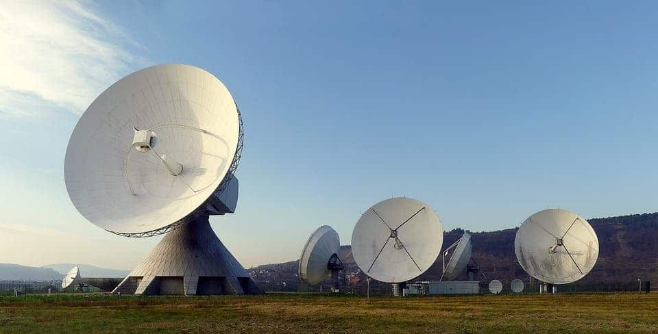
First, some history
The roots of radar technology can be traced back to the work of 19th-century German physicist Heinrich Hertz, who found that certain objects (most notably ones made from metal) can reflect radio waves. However, technological constraints of the time meant that his findings weren’t used to build a working device until the early 20th century — in the form of Christian Hülsmeyer’s Reichspatent Nr. 165546 or “Telemobiloscope,” a device used to avoid ship collisions in fog. In essence, this patent had all the makings of modern radar, albeit in a very primitive and incomplete form.
Modern radar was developed during the second world war. The word “radar” is an acronym which stands for radio detection and ranging, and it does exactly that — the device uses radio waves to determine the relative direction and distance at which an object can be found. This technology had great military potential and so, during the conflict, several nations developed radar systems independently and in great secret from one another. The term was coined by the US Signal Corps when it was developing the system for the Navy. After the conflict, radar technology was released for civilian applications, and it has changed our lives ever since.
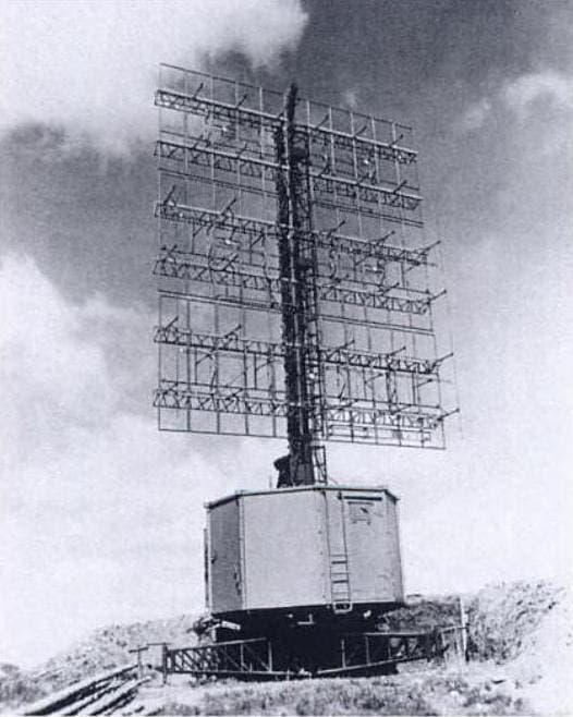
Image via The US National Archives and Records Administration.
Today, this technology unites the world and lets us explore farther than ever before: it allows our planes to fly and land safely in any conditions and helps our ships navigate and avoid crashing each other. Meteorologists use radar to track weather phenomena and give accurate forecasts. Astronomers use it to peer into the depth of space. And it’s not only used to cover huge distances and detect massive ships or planes — NASA uses radar to scan the launch pads at the Kennedy Space Center to make sure there aren’t any birds present that might cause accidents. Biologists use it to track birds and insects migratory patterns for their studies, civil engineers use it to track structural defects in buildings, and geophysicists use a specialized radar antenna to study subsoil.
Image credits NOAA/ Wikipedia
So how is radar able to do all these amazing things?
Seeing with no light
Again, in broad strokes, radar works similarly to the human eye — but there are some key differences.
For you to see something, light has to travel from a source to an object, reflect off of it, and then be picked up by the cells in your retina. Although radar uses electromagnetic waves outside of the visible spectrum (radio waves) instead of light, it still relies on the same wave-reflect-capture process. Radio waves travel at the same speed as light but have the lowest frequency of the spectrum (meaning they have the longest wavelength). Light has wavelengths of about 500 nanometers (about 100–200 times thinner than a strand of hair), and the radio waves used by radar typically range from about a few centimeters to a meter, so they’re about a million times longer than light waves.
Image via Wikipedia.
Another key difference is that radar doesn’t always stay in capture mode, as the human eye does — it also emits its own signal, acting first as a source and then as a receptor of radio waves for fractions of a second at a time. While light continuously enters your eye, radar “sees” in short bursts while it records the return signals.
Let’s take the example of an air traffic control tower on a foggy night. The operators can’t see the planes overhead because it’s too dark, and they can’t use a flashlight to peer up at them because of the fog. But radio waves can pass through the fog — the radar emits intermittent pulses of radio waves then “listens” to pick up for the return signal that bounces off of objects within its range. By measuring the time between the emitted and returned signal it then determines where the reflectors — and, thus, the objects — are located, thereby helping them land the planes.
Radar can be used to determine the distance, direction, direction of travel, and altitude of an object. If a reflector is massive enough — think shorelines here — radar can even make out its shape. Doppler radars (the ones the cops use in their radar guns) can even tell an object’s speed by analyzing the difference between the emitted signal and the one that returns to the device.
How does it do that?
No matter what it’s going to be used for or where it’s going to be installed, all radars are formed from the same basic set of components: a device used to generate radio waves, something to emit them, something to receive them, and an interface to display the information to an operator.
A piece of equipment known as a magnetron is used to generate the radio waves employed by the radar system. It actually produces microwaves (which are very high-frequency electromagnetic waves) very similar to those your microwave oven churns out but are much more powerful since they have to travel vast distances.
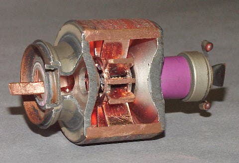
Image credits HCRS Home Labor Page / Wikipedia.
An antenna first acts as a transmitter and relays these waves in a focused direction — the antennas are usually curved to focus the beams into a narrow beam. Usually, these antennas are affixed to rotating platforms so they can be used over a wide area. The waves travel at the speed of light until they hit something and then return to the antenna at the same speed (this reflected beam is sometimes called an “echo.”) This is what allows radars to detect even fast-moving objects at long ranges. Because the energy travels at the speed of light both away from and towards the antenna, it can travel a distance of 100 miles (160 km) in just thousandths of a second.
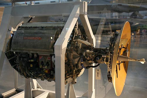
Image credits Cliff / Flickr.
During this time, the antenna switches from an emitter to a receiver — usually, antennas emit radio waves for a few thousandths of a second, then wait for reflections for up to several seconds at a time before transmitting again. This is because an antenna cannot recieve whilst emitting, and vice-versa. A piece of hardware known as a duplexer switches the antenna between these two roles. The waves picked up by the antenna are fed to a computer that processes them and displays them in a way that an operator can understand — these are the blips you see on Hollywoodian radar-green screens, and the line is the orientation of the antenna. This step also involves filtering out surplus information (or noise) such as reflections from the ground, buildings or other elements that don’t need tracking.
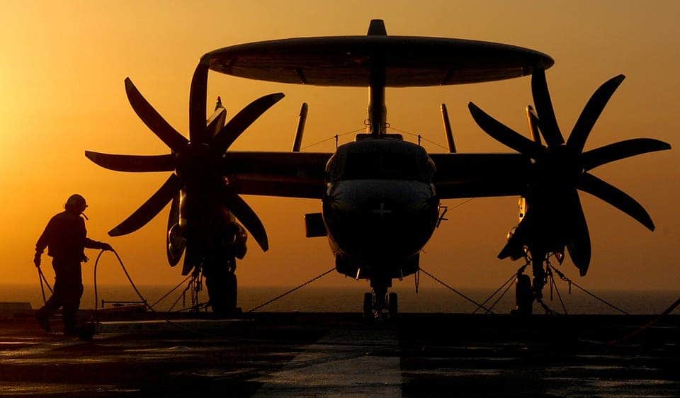
Image via Pixabay.
But my eyes can’t see everything — can radar do that?
No. By definition radar requires an echo to be formed by an object so it can detect it, so surfaces that absorb radio waves or allow them to pass right through can’t be picked up by these systems. Military research has also shown that certain fuselage shapes tend to redirect radio waves as opposed to reflecting them, which would make a vehicle, airplane or ship partially or fully invisible to radar.
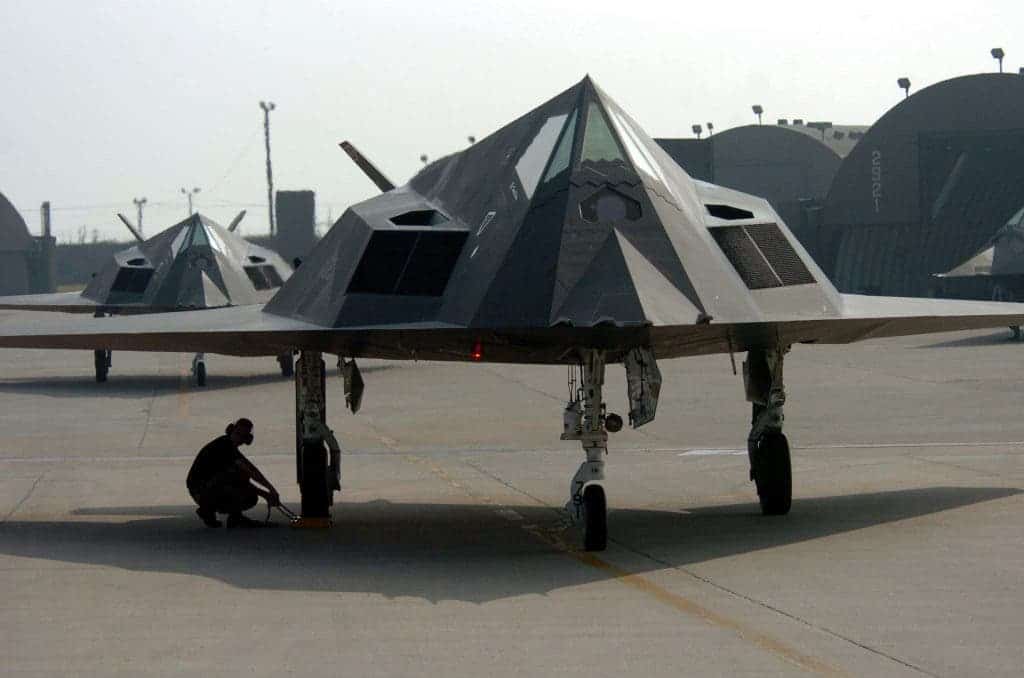
Image credits Master Sgt. Val Gempis, U.S. Air Force / Wikipedia.
One other trick you can use to avoid radar detection is to fly close to the ground, which is known to airmen as a nap-of-the-earth run because an airplane flying very close to the ground could avoid detection by using the terrain as cover from incoming radio waves. It’s a very dangerous maneuver, putting the craft at risk from crashing into the terrain or power cables. Another disadvantage is that the crafts become very easy to spot from the ground — helicopters perform NOE crafts at a few meters above the ground, while jet fighters usually stay at about 50-60 meters in altitude.
Also, while concentrated radio waves can pass through objects that light can’t penetrate, processing the echo back into any meaningful information is extremely difficult, although we’ve seen some fruitful efforts in this area. So in theory, large enough slabs of concrete could mask an object from radar — although the huge chunks of concrete would be pretty conspicuous, as well as heavy, so that kind of defeats the purpose.
Phew, that was a long read, but the next time a cop pulls you over for a speeding ticket, start explaining how his radar gun works. Who knows, you might wiggle out of a fine.
What Is Radar?
RADAR stands for RAdio Detecting And Ranging and as indicated by the name,
it is based on the use of radio waves. Radars send out electromagnetic
waves similar to wireless computer networks and mobile phones. The signals
are sent out as short pulses which may be reflected by objects in their
path, in part reflecting back to the radar. When these pulses intercept
precipitation, part of the energy is scattered back to the radar. This concept
is similar to hearing an echo. For example, when you shout into a well,
the sound waves of your shout reflect off the water and back up to you.
In that same way, the pulse reflects off precipitation and sends a signal
back to the radar. From this information the radar is able to tell where
the precipitation is occurring and how much precipitation exists.
Components Of The Radar
Radars in their basic form have four main components:
- A transmitter, which creates the energy pulse.
- A transmit/receive switch that tells the antenna when to transmit
and when to receive the pulses. - An antenna to send these pulses out into the atmosphere and receive
the reflected pulse back. - A receiver, which detects, amplifies and transforms the received
signals into video format.
The received signals are displayed on a display system.
Radar output generally comes in two forms: reflectivity and velocity.
Reflectivity is a measure of how much precipitation exists in a particular
area. Velocity is a measure of the speed and direction of the precipitation
toward or away from the radar. Most radars can measure reflectivity but
you need a Doppler radar to measure velocity.

The Science Of Radar
- Reflectivity
-
The physics behind radar has its roots in wave theory. The German Heinrich
Hertz discovered the behaviour of radio waves in 1887. He showed that
the invisible electromagnetic waves radiated by suitable electrical circuits
travel with the speed of light, and that they are reflected in a similar
way. In the following decades these properties were used to determine
the height of the reflecting layers in the upper atmosphere. This is why
data received from the radar is called reflectivity. - Doppler
-
Some 40 years earlier in 1842 the Austrian physicist Christian Doppler
had discovered what is now called the Doppler effect. This is the theory
that sound waves will change in pitch when there is a shift in the frequency.
An example of this would be an ambulance siren, which has a higher pitch
when it is approaching, but a lower pitch if it is travelling away. With
Doppler’s theory you can calculate how fast the ambulance is moving based
on the shift in the siren’s frequency. This theory is used by Doppler
weather radar to determine the speed of precipitation in the atmosphere,
toward or away from the radar. Since precipitation as it falls generally
moves with the wind, you can determine the wind velocity with Doppler
technology.
History Of The Radar
Although already invented, radar was further developed during World War
II, with work on the technology stimulated by the threat of air attacks.
Radar had many uses during the war — it was used for locating enemy ships
and aircraft, to direct gunfire, and to aid ship and aircraft navigation.
Though the military continues to use radar, the technology was released
to the public after World War II and was quickly used by many other industries.
Radars are now used to help navigate ships in fog and airplanes in bad
weather. Radar can detect a speeding car and track a satellite. Most importantly
for meteorologists, radars can detect all sorts of atmospheric phenomena.
Radar Images
Weather radar images are generally a map view of reflected particles
for a specified area surrounding the radar. Depending on the intensity
of the precipitation, different colours will appear on the map. Each colour
on the radar display will correspond to a different level of energy pulse
reflected from precipitation.
The strength of the pulse returned to the radar depends on the size of
the particles, how many particles there are, what state they are in (solid-hail,
liquid-rain) and what shape they are. After making many assumptions about
these factors and others, the approximate rain rate at the ground can
be estimated. In fact, the most reflective precipitation particles in
the atmosphere are large and usually have a liquid surface (water-coated
hailstones).

Radar Errors
Radar images will not always accurately reflect what is occurring in the atmosphere
and not everything you see on the radar will be precipitation. For example,
the radar sometimes detects precipitation that occurs higher in the atmosphere
but doesn’t reach the ground. That’s why the radar may appear to show
rain when rain isn’t occurring. This is called virga.
If the radar is close to the coast and the beam is broad enough, it may
reflect off the sea and return strong reflectivity that is really just
sea «clutter». At some wavelengths the radar beam is not fully reflected
when passing through very heavy rain or hail, thus reducing or obscuring
the echo intensity further out from the radar. The presence of mountains
within the range of the radar can block part or whole of the radar beam,
thus significantly reducing the echo intensity from rain on the other
side of the mountains. This is considered «ground clutter» and can also
be produced by buildings and trees. Occasionally birds, planes, ships
and even a dense enough swarm of insects can be detected by weather radar.
This is even more common with Doppler radars due to their higher sensitivity.

As you move further away from the radar, the returned echo becomes weaker.
This occurs because as the radar beam broadens with distance, the proportion of
the beam that is filled with rain lessens and reduces the echo intensity. The
radar beam is also further from the ground with distance (partly because of the
Earth’s curvature, and partly because the beam is angled upwards by a fraction
of a degree), thereby missing the lower parts of the rain. For example, a
horizontal radar beam detects raindrops at a height of 1 kilometre above the
Earth’s surface from rain that is 100 kilometres away from the radar. Yet rain
that is 200 kilometres away from the radar will be detected at a height of 3
kilometres.

Radar Facts
The Japanese squadron that bombed Pearl harbour was detected by a prototype
Hawaiian Radar before the air raid but no alert was sent out, as nobody believed
the inexperienced radar operators!
Bats have a Doppler radar, of sorts. Their noses are able to send out a short
‘cry’ which reflects off objects in the distance and sends back an echo received
by their ears. From this the bat is able to tell if an animal is in its vicinity
and if that animal is moving towards or away from it.
Some wind changes can be seen on the radar as very thin slow moving lines. This
is because insects usually congregate around wind changes and if there are
enough of them, the radar beam will be reflected. Similarly when a swarm of bats
take off at dusk they can sometimes be tracked on the radar.