
Introduction: Wordclock
Ever since first seeing QLOCKTWO by Biegert & Funk a couple of years ago, I have wanted a word clock on my living room wall. The original, however, somewhat exceeds my yearly clock budget, so I started looking for alternatives.
The internet is riddled with DIY and commercial versions of this type of clock, but few are as stunningly beautiful as the original. A selection:
- QlockTwo Tribute
- Dougs Word Clocks (and his earlier attempts: one, two, three)
- Arduino WordClock
- Rainbow Word Clock
- Sleek word clock
- Makezine Small Word Clock
- … and many more, I’m sure
None of these felt «good enough», but I have found one DIY project that really stands out: Elektronika.ba’s wordclock, proving that it is possible to build your own wordclock that is as pretty as the original.
Also, here is a video of the manufacturing process of the original: QLOCKTWO manufacturing
I have decided to build my own version, taking some queues from the sources in the above and making some changes (and adding some mistakes) of my own. Along the way, I have tried to take many pictures and I have written a build report in the form of this Instructable.
The entire device is open source hardware: all drawings, photographs, schematics, PCB designs and software are available. However, if you plan to build a clock of your own I encourage you to make some changes and add some twists.
GitHub: https://github.com/wouterdevinck/wordclock
For the Epilog challenge:
What could I possibly do with a laser cutter? Oh boy, what couldn’t I do? At first I would probably make some enclosures in wood and acrylic (well, boxes basically…). When that gets old I would move on to some more advanced uses: engraving the anodized aluminium enclosure of one of my next projects (cannot tell you yet what it is, but it will be really cool!), cutting precise mechanical parts (gears a.o.), selectively removing paint from the back of a sheet of glass, … In summary: a lot of good content for many Instructables!
Step 1: Think Long and Hard
Start with a good design/plan to avoid surprises down the road! This step mainly involves some thinking and maybe some drawings.
Some of my requirements for the clock were:
- It had to be professionally looking: glass front (no acrylic), white edges to blend into the white wall, …
- Be able to control all LEDs individually, not only in groups per word, so that it can be used as a matrix to display text and numbers (e.g. date and temperature)
- Keep the cost down (but a couple 100 euros was acceptable)
- Use a professionally made PCB
Part of every project I do is to learn a new skill (or a few new skills). In this case some of the new skills I wanted to learn were designing a PCB (albeit a simple one) and preparing it of for manufacturing. - As thin a possible, no bulky frame around it
- Precise up to the minute, in words
- Be compatible with Arduino: use an ATmega328 microcontroller, running the Arduino bootloader and use the Arduino IDE and libraries to program it.
- Automatically adjust the brightness of the LEDs
I decided to build a fairly large clock: 50 cm x 50 cm (20″ by 20″) with a 16 by 16 grid of characters, with behind every character a bright white LED. This makes for a total of 256 LEDs, which I wanted to be able to control individually. I will talk about the details of the circuit in the next step, but on the drawing you can already see that I opted to use a chip specifically designed to drive an 8 by 8 LED matrix (well, I of course had to use four of those to drive a 16 x 16 matrix).
The main body of the clock would be routed out of an 18 mm (~3/4″) thick sheet of MDF, with in the front 256 conical holes and in the back a cavity for the PCBAs with LEDs and driving electronics. I also planned to close the back with a thin sheet of aluminium that could double as a heat sink for the voltage regulators and LED drivers. In retrospect, it probably would have been fine without heat sinking, but better safe than sorry (and its nice that the back is closed to protect the electronics).
The front (faceplate) is glued to the main body, which makes it hard to replace, but also makes it look good (no frame or screws or anything). It consists of three layers: a thin sheet of glass (2 mm), a black self-adhesive vinyl cutout and a diffuser (tracing paper). The vinyl sticker covers the entire sheet of glass and is stuck to the back of it. The (mirrored) characters are are cut out of the vinyl. The diffuser is sandwiched in between the vinyl and the main body. The faceplate was designed in Inkscape early in the project.
Also note the this is where I made my first horrible mistake (so that you don’t have to). When I first laid out the grid of characters in Inkscape (just a black canvas with white text in the Droid Sans Mono fixed-width font), I forgot a word. I only noticed more than a year later after the vinyl cutout had been manufactured. I dare you to look at the drawing a find the mistake. The missing word can be formed by combining parts of two other words, so the clock still works, but it will be an eyesore for years to come. Don’t be as stupid as I was, quadruple check your design!
Step 2: Schematics
Early on, I decided to use the following components (also refer to the block diagram):
- Atmel ATmega328 microcontroller
- running at 16 MHz
- with the Arduino bootloader
- Maxim (Dallas) DS3231 real time clock with built-in temperature compensated crystal
- + 3V back-up battery
- Four Maxim MAX7219 LED drivers
- each driving an 8×8 grid of LEDs
- Four Azoteq IQS127D capacitive touch sensor chips
- will need an antenna behind the glass
- one in each corner
- alternative: if Azoteq is hard to find, Atmel has a similar part
- 256 PLCC-2 (3528) Power LEDs
- I got them on eBay for around 7 USD (for 300)
- they have gotten even cheaper since: http://www.ebay.com/itm/120919795895 (.99 USD for 100)
- A buzzer
- as feedback when «pressing» the capacitive buttons
- An light sensor (LDR)
- to automatically adjust the brightness
The schematic is fairly straightforward: everything connects to the ATMega. The schematic is split in two: the main board and the led board. More about that in the next step, but for now all that matters is that there are four led boards (each with one of the LED drivers, one of the capacitive touch chips and an 8×8 LED grid) and one main board (with everything else: the micro, the RTC+battery, the buzzer, the LDR and the power supply).
- The RTC connects to an I2C on the ATmega
- The LED drivers are chained and use 3 GPIO pins for serial communication
- The capacitive touch chips each use two GPIO pins: presence and touch
- The buzzer uses one GPIO (obviously)
- The LDR uses an analog pin (the ATmega has a built-in ADC)
The main board also has five 1117 5V linear voltage regulators: one for the main board and one for each LED board. This is overkill, but the regulators stay really cool this way and its an extremely simple setup. A more efficient power supply would have stayed cool as well, but would have been more complicated.
Step 3: PCBs
There are a couple of services available to hobbyists that manufacture PCBs at a reasonable price: Seeedstudio, OSH Park and ITead are a couple examples. Having said that, a 40 cm x 40 cm board would still have been quite expensive (e.g. 1250 USD at OSH Park, for 3 copies, ITead and Seeed had/have a maximum size of 30 cm x 30 cm). I also got a quote from Eurocircuits and that was still well over 300 euros (400 USD) for one copy.
So the circuit design had to take into account that the design had to be subdivided in multiple smaller (preferably identical) boards. After playing with the online pricing calculators and looking at the block diagram for a while, I decided to use five boards in the clock:
- One cheap 5 cm x 5 cm board with the power supply, real time clock and microcontroller
- Four (identical) more expensive, yet affordable, 20 cm x 20 cm boards with an 8×8 LED matrix, the Maxim LED driver and the Azoteq capacitive touch chip (as to be close to the corner as possible).
I got 0.8 mm thick boards from Seeedstudio in China: 10 copies of the main board (want one?) and 5 copies of the LED board for 120 USD (about 90 euros) including shipping. They are pretty decent quality, especially considering the low price.
I designed the boards in Eagle, because that is what most of the open source hardware projects use (definitely not because it is good or user friendly software). I made a small mistake in the main board, but it is easy to fix with a short jumper. Other than that I could have done a much better job at designing the silk screen layers, but in the end that doesn’t really matter anyway. The pictures of front and back of the boards are annotated and hopefully clarify a couple of things.
The process of designing a PCB is a bit out of scope of this Instructable, but here is a good introduction to PCBs in Eagle: https://www.instructables.com/id/Turn-your-EAGLE-schematic-into-a-PCB/
Step 4: Glass Faceplate
I ordered a piece of 2 mm glass of 50 cm by 50 cm and had the vinyl sticker manufactured by a company called «Baby grafix» (they usually make «baby on board» decals for cars).
Before ordering the sticker, you need to prepare the file, many manufacturers ask for vector graphics in PDF or AI (Adobe Illustrator) format. I had originally used Inkscape, so I converted the text to vectors and exported the design to AI. I used a trial version of Adobe Illustrator to check the file before sending it off. Also make sure to specify to the manufacturer that you are going to apply the sticker to the back of the glass, which means they have to cut it in reverse.
Applying the (expensive) sticker to the glass is by far the most nerve wrecking step of the whole build. I used the wet application method, which I would recommend with a sticker this size. The downside of wet application is that at first it looks really bad (milky white streaks), it takes a couple of days to dry.
The pictures and annotations should provide plenty of info to complete this step successfully. The key is to work fast and watch out for dust.
At some point I would like to redo the face plate (without the missing word in my design) and use silk screening instead of a vinyl sticker. In the mean time: this is an Instructable about screen printing.
Step 5: Soldering the Four LED Boards
Soldering 256 LEDs may seem like a lot of work, but it only to me about half an hour per board. Two hours of work is quite okay considering the total amount of time spent on this project. I start by putting a bit of solder on one pad of the LED, the push it on place with tweezers (while heating the blob of solder) and then solder the other pad. There is a video in the above.
Step 6: Soldering the Main Board and Testing All Electronics
Once the LED boards are assembled they can be tested using an Arduino and once the main board is assembled and tested the whole system can be tested. Finally the five boards can be permanently attached together with solder.
Step 7: Main Body: Routing and Drilling
This step is by far the most work. And the most dusty.
- Route a shallow cavity in the back of a 50 cm by 50 cm piece of MDF, covering most of the surface. The LED board will sit in this cavity.
- Route a deep cavity for the main board. I opted to route one cavity in the wrong place and one in the right place.
- Drill 256 pilot holes
- Drill 256 10 mm holes
- Countersink the inside of all 256 holes with a small countersink (for the LED to sit in)
- Countersink the front of all 256 holes with a large (I used 25 mm ~ 1 inch) countersink
Bear in mind that MDF dust is harmful and power tool can hurt you, so wear adequate protection.
Step 8: Main Body: Painting
I covered the front of the MDF with reflective spray paint. This paint is pretty nasty, it contains Xylene, so I advise working outside and/or wearing a respirator. Also make sure to cover the surroundings, especially outside on a windy day.
I also covered the edges of the front in black paint because the vinyl sticker was slightly smaller than the glass.
Step 9: Main Body: Bringing Parts Together
Some small steps:
- Routed a hole and slot for the power jack
- Put the LDR in a hole on the bottom edge
- Hot glued a serial port connector in the back
- Had to enlarge to hole behind the o’ in «o’clock» because of the ‘
Step 10: Main Body: Edges
To clean up the MDF edges, I applied white iron-on edge banding. The pictures and annotations should clarify.
Step 11: Software
I used the Arduino IDE to program the clock and used the following libraries:
- Chronodot library (for DS3231) — https://github.com/Stephanie-Maks/Arduino-Chronod…
- LedControl library (for MAX7219) — http://playground.arduino.cc/Main/LedControl
The current code and a future updates are available on GitHub:
https://github.com/wouterdevinck/wordclock/blob/ma…
Step 12: Aluminum Back Plate (heat Sink)
I cut a thin piece of aluminium (1 m x 0.5 m x 0.5 mm) in two using regular scissors. I drilled and countersunk 12 holes to screw the aluminium back plate into the clock body. I also drilled two holes for the wall attachment.
The LED driver chips are thermally bonded to the back plate using some thermal paste and the power supply (5 regulators on the main board) is connected using thermally conductive pads (because it sits deeper).
Step 13: Touch Antennas
I made four antennas out of aluminium, one for each corner. I am still not sure what the two touch inputs on the top will be, but the ones on the bottom are to temporarily display date and temperature respectively.
The antennas are connected to the PCB with a short piece of wire. On the PCB, the trace to the test pad was cut using a utility knife.The pieces of aluminium sit in shallow cavities and are held in place with a bit of glue. The cavities are a bit deeper that the thickness of the aluminium, but that does not matter, the antenna does not need to be flush with the glass.
Step 14: Power Cable
I decided to make the power cable a little less ugly by putting it in a braided sleeve. It is red because there already some other red accents in my living room.
Step 15: Tweaks
There are a few things that can easily be tweaked:
The maximum brightness of the LEDs (brightness 15 in software):
Every LED driver chip has a current set resistor. I am still playing with the extra boards to see how bright I can go without destroying the LEDs or the chip and without using a ridiculous amount of power.
The sensitivity of the touch inputs:
If the touch inputs are to sensitive because of the large antenna, there is an extra pad on the back (C7, in each corner) for an extra capacitor on the antenna line. Refer to the Azoteq datasheet for details.
4 People Made This Project!
Recommendations
Today, I will show you how to build a Word Clock. It is basically a clock which displays time using words. I will also show you how to use a Shift Register and RTC using a microcontroller. Shift Register can come in very handy if you run out of pins in a microcontroller, so its a good thing to learn about them.

Wait no more and get right into it.
Step 1: Watch the Video!
The video has the detailed explanation of all the steps involved in the build. So watch it first to get a better grasp of the project.
Step 2: Get the Parts Required.

Arduino:
INDIA – http://amzn.to/2FAOfxM
US – http://amzn.to/2FAOfxM
UK – http://amzn.to/2FAOfxM
74HC595 Shift Register:
INDIA: https://amzn.to/2pGA8MD
US: https://amzn.to/2pGA8MD
UK: https://amzn.to/2pGA8MD
DS3231 RTC:
INDIA: https://amzn.to/2pGTxh4
US: https://amzn.to/2pGTxh4
UK: https://amzn.to/2pGTxh4
ULN2803 Darlington Transistor Array:
INDIA: https://amzn.to/2GculoX
US: https://amzn.to/2GculoX
UK: https://amzn.to/2GculoX
Step 3: Test the Shift Register.

There are four kinds of shift register – Serial In Parallel Out (SIPO), SISO, PISO, and PIPO.
We are going to use 74HC595 which is an 8 bit SIPO shift register that means it will take 8 bit serial data, and convert it into 8 bit parallel data. You might wonder why we need a shift register. Let’s see. An Uno has 14 digital I/O pins and 6 analog input pins. Even after combining them we only have 20 number of pins, out of which not all are output capable. And that is the problem because we will be working with a lot of LEDs in this project.
A shift register consumes very less pins of the microcontroller, 3 in this specific case, and can control a large number of LEDs with it, which is 8 in this case. And that’s not it. This shift register can also be daisy chained with another shift register to control even more LEDs, and the second one can be daisy chained with the next shift register and so on. What I’m trying to say is just by using three pins, you can control lots and lots of digital devices.
See pin diagram of the Shift register. Pin number 1 through 7 along with pin 15 is the parallel output data.
Like all 74 series ICs, 8 and 16 are power pins.
Pin 14 – aka serial input, Pin 12 – aka latch, Pin 11 – aka clock, are the control pins I talked about.
Pin 10 is called serial clear, and is used to clear the output of shift register, will be held high throughout the project; pin 13 called output enable, as the name implies, enables the output, will be held held low.
Pin 9 is used for daisy chaining and is connected to next 74595.
Let’s see the working. The latch is pulled down before sending the serial data. Then each of the 8 bits is sent one by one. The shift register determines that new data is coming by checking the status of the clock pin, if clock pin is high, the data is new. When all the bits are completely sent, the latch is pulled high to actually reflect the data in the 8 output pins.
To execute all of this in Arduino IDE, there is a function called shift out having four parameters (see picture). The first two are self-explaining, fourth one is the 8 bit serial data, written in binary format here. If the third parameter is MSB first, then the MSB of the serial data will be sent first and will actually be reflected in the pin ‘Qh’ of the register preceding the remaining data and if the third parameter is LSB first, the LSB will be shown in the pin ‘Qh’.
Now the current output capability of this shift register is only 20 mA per pin, and we will be needing more than that, that’s where ULN2803 comes in.
If you want to test the functioning of the shift register, I have attached a sketch in this sketch along with the pictures, just apply power, connect pin 11, 12 and 14 to any digital pins of Arduino and upload the sketch. See the video for better understanding.
Step 4: Set the Date and Time of RTC.
I connected the RTC to Arduino like any other I2C device (SDA to A4 and SCL to A5), and applied power. Then I opened the sketch attached in this step and set the parameters of the “setDS3231time” by referring the commented line just above it, to set the correct date and time of the RTC. Then I uncommented that line and uploaded the program to Arduino. Without disconnecting anything, I commented the line back again and uploaded the sketch to Arduino. Now remove power from the RTC, leave it for a minute or two, connect it to Arduino once again, and open serial monitor. If the date and time displayed on the monitor is correct, you know that the RTC is working fine.
Step 5: Make the Circuit Board.

The connection diagram is attached in this step. You can either hand solder it or order a PCB. It’s all up to you. I ordered PCB as I have once hand soldered the PCB, and it was quite time taking and the bottom was really clumsy too.
I ordered my PCB from JLCPCB.
Link for schematic and PCB: https://easyeda.com/Tesalex/Word_Clock_copy-c7c7a7…
Step 6: Prepare the LEDs.

1. Check all the LEDs with a 3V battery.
2. Chop off the top of the LED.
3. Shorten one leg of resistor and anode (longer leg) of LED.
4. Solder the short leg of resistor and the anode together.
Do this to all the LEDs you are going to use.
Step 7: Build the Backbone and Final Test.

After LEDs are done, I took a cardboard from an appliance packaging, 8×8 inch in size.
I printed the template attached t this step on a white paper and two copies on a transparent sheet, as the ink is a bit light.
Now I cut the template to actual size and stick it on the cardboard using some glue. After this, I made holes for the LEDs according to the length of the words so that they do not look dim when LEDs glow. Then I took 4 solid copper wires and stick them between two rows of LEDs. Then I pushed the LEDs in the holes keeping the resistor led close to the copper wire. After this, I soldered the resistor to the copper wire and soldered the cathode of LEDs of the same word together. Then I chopped off excess leads.
Now I took three ribbon cables having eight wires each and on one end, I soldered male headers and other end will be soldered to LEDs. These headers will then go the female headers of the PCB. But which wire will be soldered to what word? Attached with this step is the sequence of the headers connection according to the program I have written. Therefore, first wire of header 1 should go to the word twenty five, second to thirty, first wire of second header to one and so on.
Now you will notice that the last 4 headers are not connected to anything and you might notice that the copper wire at the back must be soldered to 5 Volts. So, I shorted them all out and connected them to the very last header and if you remember also connected the last female header to Vcc or 5 Volts. The word “it is” and “o’clock” must be on always therefore I soldered them to second last pin of the header and on the PCB I grounded them. Lastly, the “minutes” word is not always on, and needs controlling too, so I soldered it to the fifth pin of third header, and the reason why we shorted pin 3 to fifth female header while assembling the PCB as pin 3 controls the word minute in the program I have written.
That being said, it is now time to check the functioning by connecting the headers at their respective places, uploading the sketch to Arduino and applying 5 volts and mine is working great. I quickly soldered a DC barrel connector to the power pins as I’ll be using a 5 volt adapter, otherwise I would have used the 7805, for which I have already left a space in the PCB.
Step 8: Remove the Light Bleeding.

For removing the light bleeding to other words I used a 1 cm height cardboard piece and stick it using some hot glue between every word. I started from the center then came all the way out. After this I measured and cut the cardboard for each place and then stick it again using two drops hot glue.
Step 9: Put Everything in the Enclosure.
I made an enclosure out of a 12 mm MDF having internal dimensions 8×8 inch and made sure that the cardboard fits in perfectly. I also cut an acrylic sheet of the fitting size and keep in mind that this time, it must not be much thick. I attached the acrylic sheet and also made a hole for the barrel jack on one side of the enclosure.
Now I brought each of the vinyl to size by removing the corners and afterwards stacked them together and stapled them on two opposite sides. On the back of the vinyl, I stick and opaque tape to the words which were of no use.
Then I dropped the vinyl to the enclosure and also the cardboard I have prepared and powered it, and everything looks great.
I cut a piece of cardboard from corners so that it is easy to remove them if required.
Few changes (not really necessary):
I changed the power wire to a thicker gauge so that it can carry the current required with ease and also connected the RTC using a female header (recommended) as it sometimes require to change the date and time. You can add hot glue to hold the cardboard in place if required, but mine has enough friction to just be there even in an earthquake.
For More Details: DIY Word Clock
It can be difficult to explain a SaaS Operations Platform to people.
In many ways, platforms are best explained through hands-on experience, not verbally. So we spent a lot of time thinking about how to get people to understand exactly what Tulip does in a single experience.
What we landed on was a manual-assembly experience where people build their own word clock from start to finish.
What this meant, in practice, is that we needed to build that work clock from scratch, in house. So here’s how we designed the product behind our latest demo.
What is a Word Clock?
A word clock is just what it sounds like. It’s a clock that tells time by spelling out the time in script rather than by the classic dial design or with digital numbers.
Why the Word Clock Assembly?
We created this word clock as a way to demonstrate multiple different facets of Tulip – smart work instructions, device integrations, IoT connectivity, and analytics. A participant gets to see everything that sets Tulip apart in one demo.
In the demo, each potential customer assembles their own word clock. As they do so, they experience everything a factory operator would, and, in the process, they see the power and flexibility of Tulip. In the end, participants get to keep the final word clock as a gift.

Designing the Word Clock
Building the word clock was an exercise in engineering, design, and manufacturing. We wanted an aesthetic object that cost less than $10 for everything – all electrical and mechanical parts, a power supply, and a box.
What do you need to build a word clock?
What do you need for a working word clock? Here’s a quick inventory:
- A face plate with letter cut-outs to show the time
- 2. A diffuser for the LEDs so that the light has an even distribution. If you didn’t use a diffuser, you would likely be able to see the LEDs through each letter.
- A case or a different way to hold each of the components together.
- A 3D honeycomb grid to prevent light leakage from each of the LEDs. Without this, if you lit up a single LED, the light would bleed into the other letters. This would make reading the clock impossible
- Electronics – 64 LEDs at least for an 8×8 clock and a microcontroller to drive it all
- A way to keep time that is more accurate than a microcontroller.
- The code that will make the microcontroller run as a word clock.
That is seven distinct components, each with their own unique challenges.

It can’t be that hard…
Turns out designing a word clock is easier planned than done. Here are some of the ways this task got complicated.
Iterating to a final design
Most word clocks use a laser-cut piece of metal or wood as a face plate to block the light. In searching through word clock designs, I came across some designs that used a bank printed circuit board (PCB) as both the faceplate and the diffuser of light. The silk screen and copper had been added in the negative of the letters and with a thin enough PCB, the light was able to shine through as a diffuser.
These features solved three of our problems:
- In designing a face plate, we got two of the other components for free
- We didn’t need to add a diffuser since the PCB acted as a diffuser and a face plate
- 2. We didn’t need to add a case because we could mechanically attach the back plate with electronics to the face plate
With most of the mechanical issues resolved – we needed one more thing: the honeycomb. I had our application engineer extraordinaire Justin help create a quick design in Onshape which we printed one of the Formlabs Form2 3d printers we have in our labs. We found that printing directly onto the build plate created the least amount of distortion. We were iteratively able to decide on the tolerances and create a design that fit nicely.
Since we had decided to forgo a case, we knew we shouldn’t put any electrical components on the back. This was partly for safety (we didn’t want people accidentally touching the back and shorting two things) and partly an aesthetic choice. This meant everything had to fit on the board – including the ATMega microcontroller.
If you have any questions about what this looks like under the hood, check out our Github!
For the electrical design and software – I forked a different design that used an ATmega328 (the same chip as an Arduino) and a pre-made LED block. We were able to use most of the forked code (with some minor updates to refresh-rate and letter placement). I updated the schematic and decided to do the layout in Eagle, instead of Altium, so the design would be more open-source friendly.
We added an additional feature: a Real Time Clock (RTC) and battery module that would keep the time even when the device was not powered. Often when your microwave or stove loses electrical power, the clock will be reset. This is because it doesn’t have an RTC with a battery. These little modules came with a battery and solved a bunch of design problems with respect to batteries. We program these clocks to the current time using Tulip and a serial protocol (i2c) that we connect directly to our Gateway.
With all of the seven requisite parts working, we were able to finalize the design for the complete word clock.
Sourcing the components & Mass Production
In school or as an engineer this is where the process ends – you’ve made the design and it looks good. For me, finalizing the design was only half of the process – we still needed to productize. This meant finding someone to make sourcing enough components for 500 Word Clocks – this meant 500 ATMega328s 31500 LEDs, and 4000 resistors as well as many other components.
Since we work with Contract Manufacturers for our main hardware products (Light Kit and Gateway), we were able to use these relationships during the prototyping and mass production phase. For more complicated mechanical projects, this is where productizing hardware fails – finding a manufacturer to create quality parts is difficult. Luckily because of our established relationships and the maturity of electronics assembly in China, we were able to navigate mass production with relative ease.
Sourcing the components was harder since we were very price sensitive. We didn’t want to use our typical process and have our contract manufacturer to purchase parts on our behalf. We also didn’t want to use American distributors like Digikey or Mouser because they are high-priced and require import into China
Since the BOM was small and most of the components were commodities, I did the sourcing myself. We leveraged a Chinese distributor, LCSC, for most of our parts. The parts are dirt cheap and if you pay for the fast shipping, they arrive in about the same time as North American distributors. For our key components: the LEDs and the Microcontroller we stuck with American distributors.
After resolving sourcing and getting all the parts to the factory, we were able to smoothly move into mass production and received 500 unassembled.
The Word Clock Assembly App at a Glance
Here’s a quick breakdown of the word clock app in practice.
1.) Pick-to-Lights guide operators to the RTC module bin
2.) Program the RTC
3.) Pick the baseplate and spacer
4.) Attach the RTC
5.) Complete the Assembly and plug in the clock
6.) QA the Word Clock in Line
7.) Complete Assembly!


If you want to build a word clock yourself and see what Tulip is all about, visit us at one of our upcoming shows, or schedule a demo today.
Further details on this build can be found on my site here: Word Clock
The Arduino word clock with minute resolution of time in words and linear display of seconds.
There are also modes for digital clock, analogue clock, temperature and humidity, as well as three games: Game of Life, Simon and Tetris.
The clock can be standalone or run as a slave off a master clock if required.
Without a master clock, time is controlled by the word clock’s built-in temperature compensated real-cime clock.
There is an option for PIR or doppler radar control so the clock automatically turns off when no one is in the room.
The clock measures 500mm x 500mm (19.68″ x19.68″), weighs 12lb (5.5Kg) and is designed to be wall mounted. There are touch pads in each corner to set up and control the clock.
Step 1: About Word Clocks
About Word Clocks
Word clocks tell the time using a matrix of words or numbers and letters and have been around for many years. There are a few different design types around that affect the complexity of the clock build.
The simplest use blocks of words to tell the time in five minute resolution eg O’CLOCK, 5 PAST, 10 PAST etc. These clocks only use 20 or so individual LED blocks and therefore are the simplest to construct. The main disadvantage of these clocks is they can only show the time in this set format.
The medium level clock has a 11×10 matrix of LEDs plus four addition LEDs around the outside of the clock.The Raspberry Pi controlled clock Photo 2 even has multicolour LEDs and as it has 110 individual LEDs it can display digits and basic images. These clock still use a 5 min resolution in words but often add «just gone 5 past» or almost 10 to» to increase the resolution slightly. Often the four LEDs around the corners of the frame indicate the passing four minutes to fill the gap between the 5 minute worded resolution. These clocks are reasonable complex to build and often use strips of LEDs to make the build easier.
There are commercial versions of this type of clock available.The 450mm wall hanging version cost around £1000 and features interchangeable front panels in many colours and materials as well as smaller desktop and watches are available.
256 matrix Word Clock by Wouter Devinck
The word clocks with the highest level of complexity use a 16×16 LED matrix giving a full 256 LEDs to control.These clocks have a one minute worded resolution of time as well as morning, evening, night etc. They often tell the rough temperature in words like warm, very warm, cold very cold etc.
With the 256 LEDs to play with there are huge amounts of different display modes available. These clocks are quite complex to build due to the number of connections in the matrix display. Building the LED matrix on PCBs with surface mount components allows for very slim clock bodies and makes the display construction simpler but above 500mm x 500mm the PCBs start to get expensive.
Hand building the LED matrix as in my clock needs space and 500mm x 500mm is a good starting point as this can just about accommodate the large wiring looms needed to interconnect the LEDs and display modules. Very large wall filling clocks can be built using hand built LED matrixes.
Step 2: Changes
My word clock showing change of minute
Changes
This clock is a mixture of the Wouter Devinck Clock hardware & the «Catalan» Pijuana clock software. I have not used any PCBs just ready made modules and three small Vero board circuits for the power.
The main changes are detailed below.
No custom PCBs are used in this version of the clock just cheap easy to come by prebuilt modules.
The main clock body is built from 2 x sheets of 14 mm MDF rather than a single 18mm sheet.
My clock showing setback of black rear panel
The rear sheet is 10mm smaller than the front sheet on all sides except the top so the clock appears to be only 14mm thick.
The Wouter Devinck clock is just 20mm deep including the 2mm glass whereas my clock is actually 34mm deep including the 4mm glass and 2mm dust seal on the rear. Due to the setback of the rear 14mm panel and the 1.5mm setback of the glass panel from most angles the clock only looks 14mm deep. This extra depth has allowed me to use a hand built LED matrix and wiring looms rather than 4 large PCBs. It also means I can use prebuilt maintenance friendly modules without surface mount ICs on the MAX7219 boards.
The main display is built direct to the display LEDs with no PCB so any size display is possible.TTP223 Touch Sensor Modules are used instead of Azoteq IQS127D mounted on the main boards.
The display driver boards for the MAX7219 I/C use modified LED matrix boards. These boards come complete with all components.
An Arduino Nano is used to drive the clock due to its small size.
A PIR sensor module is used to shutdown the display when no one is in the room (this can be disabled to keep the display always on).
A trimmer resistor is added to the circuit, accessible from the bottom of the clock with a small flat bladed screwdriver to calibrate the automatic display brightness.
Synchronisation to my master clock system every minute on 30 seconds. If no synchronisation pulse is available the clock will free run using the RTC. Synchronisation pulses are displayed on the main display.
The software is mainly based on the «Catalan» Pijuana version of the word clock so this has been translated into English for the display. Credits display modified from the «Catalan» Pijuana» version to show the current software version number, my name and also the year of build.
The worded temperature has been removed from the clock display and a linear seconds display added to the bottom row of the Word, Digital & Analogue clocks.
When the PIR is turned On or Off «PIR ON» or «PIR OFF» is displayed for a few seconds on the word clock display.
This clock uses a DS3231 AT24C32 I2C Precision Real Time Clock Module as per the Wouter Devinck Clock & the «Catalan» Pijuana clock. I am not keen on using the Lithium-Ion rechargeable battery that is supplied with the module. I use a non rechargeable battery and have modified the module to suit.
4mm float glass with polished edges replaces the 2mm glass. The glass is fixed to the main MDF board using Chicago Fasteners rather than glue. These also act as touch pads to control the clock and allows the glass can be removed if required.
Two dust seals are built into the clock, one on the rear panel and one behind the removable glass display panel. In clock setting Mode pressing the BOT Right button now resets seconds to 0.
The following changes to the English wording have been made to make the wording as I would say it. The way individuals say the time will vary from region to region depending on where you live/went to school etc etc. There is no correct way just the way that sound best to you.
Removed the words indicating the temperature on the word clock. These have been replaced with sync status, PIR ON/OFF and Linear display of seconds.
Changed «MINUTES» to «MINUTE» at 1 minute past and 1 minute to the hour.
Added an «A» before the «QUARTER» past and «QUARTER» to the hour.
Added the missing «ELEVEN» from Wouter Devinck clock as per his notes.
At Midday changed the time to read TWELVE OCLOCK IN THE AFTERNOON.
At Midnight changed the time to read TWELVE OCLOCK AT NIGHT. After Midnight the clock will always say IN THE MORNING.
The «O’CLOCK» is now unpunctuated and just shows OCLOCK.
Step 3: Case Design
The make up of my clock case layer by layer
As my clock does not use custom Display Matrix PCBs with surface mount components my clock case has to be somewhat deeper than Wouter’s design.
My case is 34mm deep and includes the rear dust seal 2mm, rear MDF board 14mm, front display board 14mm and 4mm float glass.
Wouter’s case right is just 21mm deep, 18mm single MDF panel and 2mm float glass.
In order to make my clock appear less bulky to the eye when mounted on the wall I have incorporated a few simple design features. Pic above shows my clock on the left and Wouter’s clock on the right. From an extreme side angle view you can clearly see my case looks bulkier.
This is offset somewhat by the rear board being black rather than white making your eye concentrate on the slim white 14mm edge. The rear board being 10mm shorter on the bottom and both sides enforces this illusion.
Above — again my clock on the left and Wouter’s clock on the right. The further towards the front of the clocks you go the shorter rear board on my clock disappears from view until only the slim 14mm front board is visible.The 4mm glass is also cut 1-2mm shorter than the front board helping to hide it from view. My bulky 34mm clock case now appears to be as slim as Wouter’s case.
Step 4: Controls
Controls
There are TTP223 touch control modules on the clock, top left, top right, bottom left and bottom right corners of the display.
The buttons have different functions depending on what mode the clock is in, see table above.
Step 5: Automatic Summer Winter Setting
Not used.
Step 6: Display Modes Clocks & Enviroment
Animation showing all dislay modes
Animation 1 above shows the 4 clock and environment modes.
The modes are in order word clock, digital clock, temperature and humidity, and analogue clock.
Animation 2 above. There is also a startup mode that scrolls through the software version number, makers name and name of the clock.
Step 7: Display Modes Games
Three classic games are coded into the clock. I have left the code as is from the Catalan Clock.
Animation 1 above Conway’s Game of Life. The universe of the Game of Life is an infinite two-dimensional orthogonal grid of square cells, each of which is in one of two possible states, alive or dead, or «populated» or «unpopulated».
Every cell interacts with its eight neighbours, which are the cells that are horizontally, vertically, or diagonally adjacent. At each step in time, the following transitions occur: Any live cell with fewer than two live neighbours dies, as if caused by underpopulation. Any live cell with two or three live neighbours lives on to the next generation. Any live cell with more than three live neighbours dies, as if by overpopulation. Any dead cell with exactly three live neighbours becomes a live cell, as if by reproduction.
The initial pattern constitutes the seed of the system. The first generation is created by applying the above rules simultaneously to every cell in the seed births and deaths occur simultaneously, and the discrete moment at which this happens is sometimes called a tick (in other words, each generation is a pure function of the preceding one). The rules continue to be applied repeatedly to create further generations.
Animation 2 above Simon
Simon memory game- try and copy the computer generated sequence.When entering your sequence double tap the last entry to end your turn.
When you fail your score is displayed on the screen.
Animation 3 above TetrisTetris is the Soviet tile-matching puzzle video game released in June 1984.This game still needs some work on the buttons to control the tiles correctly.
Step 8: Prototyping
The Clock can be prototyped and tested using the original DOT Matrix LEDs on the MAX7219 display boards.
Note this temporary modification is only required if you want to test your code on the DOT matrix displays supplied with the MAX7219 modules.
This means you can try out your software/word layout modifications in miniature before committing to the full size version. The wiring to the DOT Matrix LED will have to be modified to match the software connections.
Pic above shows how the Module is wired before modification. The modification is quite straight forward. First of all bend the following LED Matrix pins 90°, the top pins up and the bottom pins down.
Pins 16, 15, 3, 4, 10 & 11.
Insert the LED Matrix in the socket on the display PCB the above pins will now not be connected. Solder the following link wires from the back of the socket of the display PCB to the LED Matrix pins that are sticking out.
LEDA to Dot Matrix Pin 16
LEDB to Dot Matrix Pin 15
LEDG to Dot Matrix Pin 3
LEDF to Dot Matrix Pin 4
LEDE to Dot Matrix Pin 10
LEDC to Dot Matrix Pin 11
I used a multimeter and buzzed out the display module. The Table shows where the software pin number differ from the LED pin numbers on the display board.
To test your word layouts print out a miniature version of your word display 62mm x 62mm on plain white paper.
Cut the printed layout into quarters.
These will then fit over the four LED Matrix displays.
The individual LEDs will light up the letters.
Note the orientation of the LED Display boards to match the software layout.
I have kept the display rotation as the original Wouter Devinck clock in case anyone uses Wouter Devinck PCB design for my clock.
Fully working prototype on my test bench
The small push button below the temp/humidity sensor is used to test the 30 second synchronisation. The touch button modules are on the bottom left of the breadboard mounted sideways. There are not many wires on this prototype as most of the wiring is in the display matrixes. On the final clock this wiring will be done by hand to the individual LEDs.
I tried out many different word/clock designs on this board before attempting to build the final clock.
Step 9: Testing the Modified Modules
I have modified the word clock sketch to enable the MAX2719 module to be tested after the wiring mod.
All this program does id light each LED in turn from the top left to the bottom right of the matrix.
Just connect 5 wires to the NANO and MAX2719 module and power the NANO from its USB port. Load the sketch and let it run.
Just plug in each module in turn to check your wiring.
Download the test sketch from the enclosed zip file.
Step 10: Time to Word Mapping
Table above shows the Time to Word Mappings.
There are no hard and fast rules on these just set the words as you would tell the time.
In my clock I changed the following compared to the words on Wouter’s clock.
«MINUTES» changed to «MINUTE» at 1 minute past and 1 minute to the hour. Added an «A» before the «QUARTER» past and «QUARTER» to the hour.
At Midday changed the time to read TWELVE OCLOCK IN THE AFTERNOON.
At Midnight changed the time to read TWELVE OCLOCK AT NIGHT.
After Midnight the clock will always say IN THE MORNING.
These changes are very easy to implement in the clock software.
Step 11: Power
I use a common 12 volt power supply unit to drive many different types of circuits throughout my house. This 12 volt supply is then stepped down locally at each circuit with a 5 volt module to supply power for the control board and various modules.
My common power supply has 18 individually fused 12v circuits each with a 2A fuse. 9 of these are battery backed up. Clock boards also have their own on board fuse.
If you are running just this one circuit then any regulated 5volt supply will do as long as it can supply the current for your circuit use.
I have designed a power board on Vero which uses a MP1584 miniature Power supply. This converts the 12v output from my common power supply to the 5v for the clock.
There are two extra power boards constructed from Vero board.
Apart from 1 holding the buzzer they just add extra power distribution points for the power wiring of the clock.
Power Requirements
I have measured the current draw from the clock and at low brightness it uses 30mA and full brightness 250mA. This will of course vary with how many LEDs are on. On a bright sunny day the brightness levels indicated on the serial out are 10. This is around 2 thirds of the max power of the LEDs. Overall power consumption can be greatly reduced if the PIR is turned on. This will blank the display if movement is not detected by the clock.
I would use a minimum 500mA supply to power the clock. Power will depend greatly on the type of LEDs you source.
Step 12: Module Interconnections
Pic above shows how the modules are connected. Most modules connect directly to the Arduino Nano.
The MAX7219 boards only connect to the NANO via module 01. The other modules are daisy chained together.
Each 8×8 LEDs matrix is then connected to a MAX7219 module.
The bulk of the wiring is the connections between the MAX7219 modules and the LED matrixes.
Keep the distance between the NANO and the 1st MAX7219 module and MAX7219 module to modules as short as possible. Also make sure you supply power to both ends of the daisy chained MAX7219s as most of the power is drawn by this part of the circuit.
Step 13: Construction Order of Build
Order of build presuming all prototyping and software changes are completed first.
Get vinyl transfer printed.
Get glass cut.
Cut MDF Sheets front and back.
Cut holes in front sheet for LEDs.
Paint MDF Sheets.
Cut holes for sensors in glass.
Stick Vinyl transfer to rear of glass.
Cut sensor holes in MDF front board.
Cut sensor module rebates in front board.
Cut MDF back board and make 4 access holes for sensor access.
Add melamine edge strips to MDF boards, white to front board and black to rear board.
Screw back MDF board to front MDF board.
Make Vero boards, 1 power board and 2 power distribution boards.
Modify 4 x MAX7219 boards and add wiring to LEDs.
Connect at MAX7219 end only for now.
Mount all modules and Vero boards on rear of MDF front board.
Construct all 4 LED matrixes on front MDF board and solder 256 LEDs.
Wire all Batt and Earth runs from power supply Vero board and power distribution boards.
Connect all power runs to all modules.
Connect all wiring to Nano, MAX7219 modules, RTC, Temp sensor, Touch Sensors and Buzzer.
Connect all wiring looms from modified MAX7219 boards to LED Matrixes as per wiring table.
Connect a PIR module remotely from the clock and connect the PIR connection.
Connect the 30 second sync to your Master Clock (if required).
Mount the Glass front display panel using the Chicago bolts also fixing the touch sensors at the same time.
Test.
Table 1 shows the very approximate build times for this clock and will vary depending on your skill level and also any specialist tools/working space you have to hand.
You can easily add another 40 hours prototyping and programming time to that list.
Step 14: Construction Vinyl Sticker
Vinyl Sticker
The Vinyl sticker is designed in Inkscape.
Inkscape is professional quality vector graphics software which runs on Windows, Mac OS X and GNU/Linux. It is used by design professionals and hobbyists worldwide for creating a wide variety of graphics such as illustrations, icons, logos, diagrams, maps and web graphics.
Inkscape uses the W3C open standard SVG (Scalable Vector Graphics) as its native format, and is free and open-source software.
I downloaded the original Inkscape design by Wouter Devinck from his GitHub repository and then modified it in Inkscape to suit my design. I tried out many different versions on my miniature prototype before sending the final design off to be printed.
Don’t forget to get the sticker reverse printed!
I used a company called Regal Signs & Graphics who supplied my sticker in black vinyl, reverse cut, lettering weeded out and supplied with an application tape all for around £27 inc vat.
Although they are quite local to me I paid a bit more and got my sticker delivered in a nice secure cardboard tube.
I had a few problems getting the design in the correct format for their machine but in the end I sent it from Illustrator in eps format the very helpful people at Regal Signs scaled it down to the correct size for me.My Inkscape file can be downloaded here VINYL STICKER.
The Vinyl sticker came from Regal Signs with the letters weeded out so this saved me lots of time.The sticker comes with a plastic tape over the front (glass) side and an application paper on the rear. Usually you peel the from side tape off apply the sticker and then remove the application paper. I decided to leave the application paper on as it acted as a diffuser for the LEDs. As I was leaving the application paper on I trimmed off the excess paper around the sticker before applying.
The sticker application was relatively easy. Just make sure you watch a few YouTube videos on Vinyl sticker application to glass before trying it yourself.
Glass
The clock uses 4mm float glass and has been cut to exactly 500mm x500mm. As the edges are exposed the edges have also been polished.This was all done by my local glaziers for £20.
5mm holes were then drilled in the glass panel using a 5mm glass drill. Checkout YouTube videos on how to drill holes in glass.
I cleaned the glass first with acetone and made sure it was dust free (very important). I then put on some plastic gloves to make sure I did not get any fingerprints on the sticker.
I sprayed the glass with a very diluted soap and water mixture and then very slowly peeled back the plastic film from the sticker to reveal the front surface.
It is important to peel the film back slowly and at a very acute angle so the letters on the sticker stay connected to the transfer paper. Once the sticker is completely exposed apply it to the wet glass surface.
The water/soap mixture will allow you to move the sticker to the correct place on the glass. Next use a credit card and work away from the centre of the sticker to remove any air bubbles. Leave the sticker to dry overnight then from the back of the sticker cut away the vinyl over the 4 mounting holes in the glass.
Step 15: Construction Main Boards Part 1
Main Boards
Side view showing clock layers
The main board of the clock is made up of 2 sheets of 14mm MDF. The rear sheet is 10mm smaller than the top sheet on all sides apart from the top. The top has white edges while the back has black edges. When viewed on the wall the clock will then appear to be 14mm deep.
The main board of the clock is made up of 2 sheets of 14mm MDF. The rear sheet is 10mm smaller than the top sheet on all sides apart from the top. The top has white edges while the back has black edges. When viewed on the wall the clock will then appear to be 14mm deep.
On the original Wouter Devinck Clock & the «Catalan» Pijuana version a single 18mm thick sheet of MDF is used with the back routed out to make space for the PCB and components. Using 2 sheets of MDF means the backboard can be simply cut out using a jigsaw rather than the time consuming and dusty routing. The top sheet is 503mm x 503mm to give a 1.5mm overlap around the glass. This will give the glass a bit of protection from knocks.
The backboard is cut out using a jigsaw and allows 14mm of component space.
The deepest PCB including components are the MAX 7219 modules that are 10mm deep. On completion the rear board is glued or screwed to the front board.
Front Board Construction
The front board holds the 256 LEDs that shine through 6.5mm holes and wider 18mm countersunk holes to illuminate individual letters and numbers on the display.
The board is marked up to show the drilling position of in the centre of each display character. Using a 500mm display I measured my vinyl sheet and the characters are 25mm apart starting 62.5mm from the edges. I drew these lines on the MDF, the intersections being the drilling points.
I used the top edge as the datum point I measured and marked each row from this point.
This was repeated for the vertical column using the left edge as the datum.
areas to be drilled/countersunk
The intersections of the grid will be the centre point for the 6mm LED mounting holes and the 18mm countersunk holes.
Using an automatic centre punch ( use a nail or screw if you don’t have one) I punched the 256 intersection points of the grid.
Using a drill bit to suite your LEDs (6mm in my case) and using the punched holes as a guide for the drill bit drill out all 256 LED mounting holes.
The next task is to drill the 256 18mm countersunk holes using a 20mm countersinking bit.
To keep the countersunk holes at a uniform depth and width I built a countersinking jig using an off cut of wood. To make the jig a hole is drilled in the wood off cut to just fit the silver rotating bezel of my drill chuck. Using a test piece of MDF the countersinking bit is then moved in and out of the chuck until a countersunk hole of the correct diameter is made when drilling through the hole upto the chuck in the off cut of wood. Once the correct distance is found the chuck is tightened and the main board is drilled 256 times by centring the hole in the wood over the existing 6mm holes then drilling down until the chuck bezel hits the hole in the countersinking jig.
Completed front board with 256 countersunk holes and 6mm holes for the LEDs.
The board is then rubbed down and primed using MDF primer and painted white so the countersunk holes reflect the light from the LEDs.
A black edge is painted around the outside edge to hide the board as the glass is 1mm shorter all round. This setback also helps the glass disappear from view on the final clock.
Four 5mm holes are then drilled in the corners to take the Chicago Fasteners. The Chicago Fasteners hold the glass in place, hold the touch sensors and provide a touch sensitive pad on top of the glass. The fasteners have 3mm shafts and will have a small bit of rubber tape wrapped around the shafts to protect the glass.
Turn the board over and drill a rebate with a forstner bit to take the four touch sensors. This hole will be offset from the hole drilled in the previous step.
Wall Mounts
The clock is fixed to the wall by two metal picture hanging mounts.
These are recessed into the frame so the highest point of the bracket is level with the frame.
Two 2″ countersunk No6 screws sit in these bracket and hold the clock to the wall with a bit of tension so the dust seal is compressed.
Step 16: Construction Touch Sensor Mounting
cutaway section through Chicago Fastener
The touch sensor modules are fixed to the front panel using the Chicago Fastener bolts. The Chicago Fastener bolts then act as touch sensors.
A 5mm hole is drilled through the sensor pad on the module to allow the Chicago Fastener bolt to pass through.
The sensor pad is insulated by the MDF panel and a plastic washer.
The touch pad on the sensor module has a 5mm mounting hole drill through the sensor.
Touch sensors in rebates behind rear panel. Holes drilled into rear panel allows access to the Chicago Fasteners that hold the sensors/glass front in place.
Clock front panel with four Chicago Fastener tops acting as touch plates.
Step 17: Electronic Components & Modules
ATmega328 pin connections in case you want to prototype the circuit on an Arduino Uno. Note BST pin 07 is not used.
Pin label numbers refer to Arduino IDE numbers.
Arduino Nano Pin Connections BST not used
LEDs
Make sure you purchase your LEDs from a good source. These LEDs will be on for many hours a day. I have has problems with LEDs failing after a few weeks use.
My LEDs Specs
5mm White Flat Top LEDs offering a pure and consistent colour with a wide angle ultra bright light output.
Colour : White
Quantity : 256
Lenses Type : Round Flat Top
Crystal ClearBrightness : 13000mcdForward
Voltage : 3.2v — 3.8v
Forward Current : 20mA (typical), 30mA (Max)
Viewing Angle : 120 degrees
DHT22 Temperature & Humidity Sensor
The DHT22 is a basic, low-cost digital temperature and humidity sensor. It uses a capacitive humidity sensor and a thermistor to measure the surrounding air, and sends out a digital signal on the data pin.
You can only get new data from it once every 2 seconds, so sensor readings can be up to 2 seconds old.
Simply connect the first pin on the left to 3-5V power, the second pin to your data input pin and the right most pin to ground.
To prevent the temperature of the inside clock case being measured the top and left side vent of the DH22 are covered over with tape. This also stops dust being drawn into the clock case.
View of the lower edge of the clock from the rear showing the air circulation vents
The DHT22 is mounted with its right open side mounted tight against the lower rear cover.Two small holes are drilled in the lower edge of the rear MDF board to allow air from the room to circulate around the sensor.
Arduino NANO
PowerThe Arduino Nano can be powered via the Mini-B USB connection, 6-20V unregulated external power supply (pin 30), or 5V regulated external power supply (pin 27). The power source is automatically selected to the highest voltage source.
Memory
The ATmega328 has 32 KB, (also with 2 KB used for the bootloader.
The ATmega328 has 2 KB of SRAM and 1 KB of EEPROM.
Input and Output
Each of the 14 digital pins on the Nano can be used as an input or output, using pinMode(), digitalWrite(), and digitalRead() functions. They operate at 5 volts. Each pin can provide or receive a maximum of 40 mA and has an internal pull-up resistor (disconnected by default) of 20-50 kOhms. In addition, some pins have specialized functions: Serial: 0 (RX) and 1 (TX). Used to receive (RX) and transmit (TX) TTL serial data. These pins are connected to the corresponding pins of the FTDI USB-to-TTL Serial chip.
External Interrupts: 2 and 3.
These pins can be configured to trigger an interrupt on a low value, a rising or falling edge, or a change in value. See the attachInterrupt() function for details.
PWM: 3, 5, 6, 9, 10, and 11. Provide 8-bit PWM output with the analogWrite() function.
SPI: 10 (SS), 11 (MOSI), 12 (MISO), 13 (SCK). These pins support SPI communication, which, although provided by the underlying hardware, is not currently included in the Arduino language.
LED: 13. There is a built-in LED connected to digital pin 13. When the pin is HIGH value, the LED is on, when the pin is LOW, it’s off.
The Nano has 8 analog inputs, each of which provide 10 bits of resolution (i.e. 1024 different values). By default they measure from ground to 5 volts, though is it possible to change the upper end of their range using the analogReference() function. Analog pins 6 and 7 cannot be used as digital pins. Additionally, some pins have specialized functionality: I2C: 4 (SDA) and 5 (SCL). Support I2C (TWI) communication using the Wire library (documentation on the Wiring website).
There are a couple of other pins on the board: AREF. Reference voltage for the analog inputs. Used with analogReference(). Reset. Bring this line LOW to reset the microcontroller. Typically used to add a reset button to shields which block the one on the board.
Communication The Arduino Nano has a number of facilities for communicating with a computer, another Arduino, or other microcontrollers. The ATmega328 provide UART TTL (5V) serial communication, which is available on digital pins 0 (RX) and 1 (TX). An FTDI FT232RL on the board channels this serial communication over USB and the FTDI drivers (included with the Arduino software) provide a virtual com port to software on the computer. The Arduino software includes a serial monitor which allows simple textual data to be sent to and from the Arduino board. The RX and TX LEDs on the board will flash when data is being transmitted via the FTDI chip and USB connection to the computer (but not for serial communication on pins 0 and 1). A SoftwareSerial library allows for serial communication on any of the Nano’s digital pins. The ATmega328 also support I2C (TWI) and SPI communication. The Arduino software includes a Wire library to simplify use of the I2C bus. To use the SPI communication, please see ATmega328 datasheet.
TTP223 Touch Sensor Module
The touch Sensor Module is bolted to the front panel using the glass mounting bolts. The bolt goes through a 5mm hole drilled in the middle of the sensor.Note the mounting bolt is touched to trigger the sensor but is insulated from the sensor itself through plastic washers. Four of these modules are used in the clock one mounted on each corner of the glass.
TTP223 Touch Sensor Module schematic
Note the LEDs are not required and are removed from the modules (just break them off) to save power.
DS3231 AT24C32 I2C Precision Real Time Clock Module
My clock uses a DS3231 AT24C32 I2C Precision Real Time Clock Module.The module comes supplied with a Lithium-Ion rechargeable battery see diagram below. I use a non rechargeable battery so have removed resistor R5 from the module.
location of R5 on the DS3231 module
charging Resistor R5 removed
MAX7219 Display Module
MAX7219 Display Module with LED Matrix in place
MAX7219 Display Module with LED Matrix removed ready for use in this clock
MAX7219 LED current limiting
The max current through the LEDs is set by a single resistor R1 on the module. The value of resistor can be found from the table below.
The module comes with a 10K resistor preinstalled but this can be removed and a resister to match your LEDs current added in its place. My LEDs Forward Voltage is 3.2v — 3.8v @ 20mA. They can handle 30mA max but for long LED life 20mA is best. I have used 22KΩ resistors which will limit the current to around 20mA when the light levels are at their peek.
See setting automatic brightness levels.
1088AS LED Dot Matrix display
1088AS LED Dot Matrix display view of lower edge Pins 1 to 8 left to right.
This is used for prototyping and is not required in the final project.
LDR
An LDR is used to sense the ambient light levels. The LDR is around 500Ω in bright light and 10MΩ in the dark.
The LDR is positioned underneath the clock on the rear MDF panel.
Next to the LDR is a hole to give access to the trimmer resister to calibrate the LED brightness control.
Component List
Add PIR or Doppler Radar Module as required
Step 18 Dust Seals
To prevent ingress of dust two dust seals are fitted.
On the rear MDF board a 2mm soft foam rubber dust seal is fitted. When the clock is hung on its hanging hooks the seal is under pressureand seals the back of the clock to the wall.
The seal is self adhesive and is fitted with a 5mm gap to the edge of the rear MDF board.
Front dust seals in position (just visible)
On top of the front board to prevent dust getting under the glass a strip of self amalgamating rubber is fitted 5mm from the board edge.
To prevent the glass from cracking when the Chicago bolts are tightened 4 small square of rubber are also fitted around the holes in the glass.
I punched holes for the Chicago Bolts in the rubber with a leather punch.
Step 19: Schematic
Nano Connections
The connections to the Arduino Nano. Download the full size file from the hardware section
MAX2719 connections
The 4 MAX7219 modules and the connected LED matrixes.
Note the LED display matrixes are rotated anti-clockwise 90 degrees from each other starting from display matrix 01.Display Matrix 01 input is wired to the Arduino CLK, DIN and LOAD the output is taken to the input of Display matrix 02 etc etc.
Step 20: Wiring Building the LED Matrixes
Module Locations
The module locations are shown above. The four sensors are located in the recesses on the main board behind the rear board. Holes are cut into the rear board to allow access for fit the Chicago Bolts/Sensor pads.
The four MAX7219 Display Modules are soldered together and are mounted in the centre top of the board. This keeps the data links between the boards as short as possible.
The Arduino Nano is mounted on the left of the MAX7219 Display Modules and the RTC on the right. The RTC battery holder on the base of the RTC module is recessed into the main board.
The Vero board containing the power module is located on the lower part of the board. There are two power distribution boards mounted on the top of the clock. The main 5v 2A feed cable is taken to both of these boards and power is then distributed to the other boards from these points.
The MAX7219 board power is fed from the left board and daisy chained through each board then taken out the forth board to ensure they are fed with 0v and 5v from both ends.
The LED locations are shown. The LED matrixes each contain 64 LEDs and are labelled 1 to 4.
These correspond to the 4 MAX 7219 modules mounted above numbered 1 to 4 left to right. Note this is the rear of the clock so number will be revearsed.
Cathode Bus Pin locations
The LED Matrixes are built up off 2 types of BUS Bars per module. A Cathode Bus at 10mm high and an Anode BUS bar at 2mm high.
There are 8 Cathode and 8 Anode BUS Bars per module. Each module has 16 x 15mm panel pins hammered into the board in the position shown to support the 10mm high Cathode BUS.
Countersunk hole locations reletive to bus bar support pins
The 15mm panel pins are hammered in 5mm (I used a 10mm piece of metal bar as a gauge) leaving 10mm as Cathode BUS bar support pins.
As shown above the pins correspond with the thick parts of the board not the recess for the LEDs on the front of the board. Note the LED recess is on the front of the board and can’t be seen from the back.
0.9mm copper wire is then soldered to each pair of pins to form the Cathode BUS Bar.
Note the rotation of each module and also the modules are in reverse as it is the back of the board the LEDs are connected to.
The Anode BUS Bars are shown below in Red and are supported off each LED Anode about 2mm off the MDF board. No Pins required.
Cathode Black & Anode Red Bus bars
Both Cathode & Anode BUS Bar locations are shown below.
Each LED is connected to an Anode and Cathode of the Matrix.
Step 21: Wiring the LEDs
LEDs
Diagram showing Bus Bar layout with panel pins supporting the Cathode Bus. This module has horizontal Cathode and vertical Anode Bus Bars.
Close up section of Module wiring.The Cathode BUS Bars run vertically and the Anode BUS Bars run horizontally on this module. The Anode & Cathode BUS Bars have an 8mm vertical separation.
LED Matrix Wiring Schedule
The LEDs are connected to the matrixes and MAX7219 modules from the rear. The LED positions will be reversed and of course rotated 90° relative to the next module. This makes it very complicated connecting the correct LEDs and Bus bars from the rear of the board. The table below shows the LED positions in the blue boxes with the BUS Bar matrix position in black around the outside as they appear from the back of the front MDF board.
The LEDs are bent in a jig to keep the position in the display constant and to speed up construction. Each LED has four bends two on each leg that’s 1024 in total! The Cathode leg is bent 90° from the Anode.
Rear left of clock showing completed wiring
The Matrix grids are wired to the corresponding pins on the MAX7219 modules according to the layout table.
There are 16 wires to each module.
Table 1 Module LED Matrix Wiring Colour Code is shown above.
Each Module has 16 wires connecting it to the LED Matrixes. I have used 50pr 0.5mm cable so the last 14pr colours are duplicated. On Mod 4 I went out of order and missed out the Sl/Vi at the start so have put it in at the end.
Step 22: Wiring Modifying the MAX7219 Modules
Before wires can be connected to the MAX 2917 modules they will need to be modified.
Two sets of 8 90° pin connectors will to be soldered to the lower edge of the existing LED matrix connector.
Modified MAX7219 module with 90° pin connectors soldered in place to the bottom of the old LED Matrix connectors.
Wires are taken away from these points to the LED matrix on the main MDF board as per the LED Matrix Wiring Colour Code table on the previous step.
Side view showing the pins soldered to the side of the old LED Matrix connector pins just above the PCB.
Note if your MAX7219 Module does not have surface mount components the 90° pin connectors may need to be trimmed back so they don’t foul R1, C1 or C2.
MAX7219 LED current limitingThe max current through the LEDs is set by a single resistor R1 on the module. The value of resistor can be found from the table below.
The module comes with a 10K resistor preinstalled but this can be removed and a resistor to match your LEDs current added in its place.
My LEDs Forward Voltage is 3.2v — 3.8v @ 20mA. They can handle 30mA max but for long LED life 20mA is best. I have used 22KΩ resistors which will limit the current to around 20mA when the light levels are at their peek.
Note this sets the max current through your LEDs actual brightness is controlled by the LDR/software/ trimmer resistor and will usually be far less than this.
Setting Automatic Brightness Levels
The clock automatically senses the ambient light and adjusts the LEDs accordingly.
When first installed the clock will need to be calibrated to the maximum light levels in its actual location.
Connect a mobile, laptop/tablet etc via a suitable cable to the mini USB port of the clock and open an app to monitor the serial port.
I use Slick USB 2 Serial Terminal on my S7 via an OTG cable and USB to mini USB cable.
The clock will reboot and after the initial start screen you will see the following data updating down the screen.
You don’t need to worry about lightReading or constrained lightReading+hyster just light reading, and bright.
With the clock in position and the ambient light at its maximum levels carefully insert a flat bladed jewellers screwdriver into the access hole just to the right of the light sensor.
Turn the screwdriver slowly until the light reading = 600 (or your level set in brightness.cpp) and bright = 15.
Your clock will now go to max brightness when the ambient light is at its maximum.
If you turn the screwdriver too far the light reading will go over 600 but the bright reading will not increase.
If you want the clock to be dimmer right across the range of ambient light levels adjust the light reading to a level less than 600 at max ambient light levels.
Note when bright=15 this will output the max current to the LEDs. The max current is set by R1( RSET) on the MAX7219 module and this should be chosen for your type of LED used in the display.
Step 23: Wring Mini USB Port
To allow adjustment/checking of light levels and programming of the clock a Mini USB socket is cut into the right hand side of the rear MDF sheet.
I have used a 25cm 90° Right angle Mini USB Male to Female Extension Cable and stripped back the insulation sleeve and shielding to expose the wires. This allows the cable to bend around the sharp angles and tight spaces of the enclosure.
Step 24: PIR Controlled Display Shutdown
This is optional as a Doppler Radar module can be fitted inside the clock instead.
See next section.
The PIR when enabled on the word clock menu (bott left PIR On, bott right PIR Off) turns on the display when movement is detected in the room.
When no movement is detected the display turns off after a set period of time. When the PIR is enabled the displays shows «PIR ON» and when disabled (display always on) it shows «PIR OFF» Note when the PIR is not enabled the display is always On.
The PIR module is fitted remote from the clock in a modified chrome light switch box. The box is cut into a plasterboard wall and also contains a switch to turn the clock off. The module itself is very small and can be mounted in a tiny enclosure if you don’t want it on show. It will not work behind glass so if you wanted to mount it on the clock a hole would need to cut in the glass. This is very easy to do with a large hole cutter.
A blank chrome switch plate and back box are used to house the power switch and PIR module.
Two holes are drilled in the blank switch plate for the power switch and PIR lens.
The hole are centre punched, pilot drilled and then drilled out just big enough for a step cutter to fit through. The hole for the PIR diffuser is cut just big enough for the lens to go through with a friction fit.
The completed switch plate.
A bit of hot melt glue is used to make sure the module does not fall out
The 12 volt supply +ve is terminated on the switch with the 0v terminated on the earth screw.
12 volts is then fed back upto the clock PSU Vero board from the other side of the switch and again the earth screw. 5 volts are fed from the clock PSU Vero board to supply the PIR module.
The 5 volts and PIR sensor wire to the clock terminate on PCB header sockets. These are is plugged into the PIR Module header pins. The sync cable is terminated on a header pins and connects to the Master Clock 30 second sync cable via a single header socket.
The PIR has 2 trimmer resistors for adjusting sensitivity and also length of time the PIR & display stay activated.
PIR On/Off Control: The PIR is turned on and off in word clock mode by touching the bottom left sensor to turn the PIR on or by touching the right sensor to turn the PIR off. Note when the PIR is set to off the display stays on permanently. When you change the PIR setting the work «PIR ON» or «PIR OFF» is displayed for 5 seconds.
When initial power up the default is PIR off if you switch the PIR On straight away the display will go off as the PIR takes a minute or so to initialise before detecting movement.
Photo 6 & 7 «PIR ON» or «PIR OFF» are displayed for 5 seconds when PIR setting is changed.
Step 25: Doppler Radar Control Option
Optional Doppler Radar Module can be added in place of the PIR above.
Microwave Radar Sensor Module RCWL0516
The Doppler Radar when enabled on the Word Clock menu (bott left PIR On, bott right PIR Off) turns on the display when movement is detected in the room. A check is made for motion on every quarter hour. When no movement is detected the display turns off until movement is detected again.
When the PIR is enabled the displays shows «PIR ON» and when disabled (display always on) it shows «PIR OFF» Note when the PIR is not enabled the display is always On. Unlike PIR modules the Doppler Radar module can see through glass and plastic and is fixed into the case of the clock behind the glass and PVC sticker. The module has a range of around 5m or 16′ 5″.
Doppler Radar Module fixed inside the case. A hole is drilled in the front panel to allow the module to monitor the room.
Front panel showing hole through to the Doppler Radar module microwave sensor.
The module is hidden from view behind the PVC sticker and glass.
Clock fitted with Doppler Radar Sensor. No external sensor panel is required with this option
Step 26: PIR/Doppler Radar On Off Control
The PIR is turned on & off in word clock mode by touching the bottom left sensor to turn the PIR on or by touching the right sensor to turn the PIR off.
Note when the PIR is set to off the display stays on permanently.
PIR ON is displayed for 5 seconds
PIR OFF is displayed for 5 seconds
When you change the PIR setting the work «PIR ON» or «PIR OFF» is displayed for 5 seconds.
When initial power up the default is PIR off if you switch the PIR On straight away the display will go off as the PIR takes a minute or so to initialise before detecting movement.
Step 27: Setting Automatic Brightness Levels
The clock automatically senses the ambient light and adjusts the LEDs accordingly.
When first installed the clock will need to be calibrated to the maximum light levels in its actual location. Connect a mobile, laptop/tablet etc via a suitable cable to the mini USB port of the clock and open an app to monitor the serial port. I use Slick USB 2 Serial Terminal on my S7 via an OTG cable and USB to mini USB cable.
The clock will reboot and after the initial start screen you will see the following data updating down the screen.
You don’t need to worry about lightReading or constrained lightReading+hyster just light reading, and bright.With the clock in position and the ambient light at its maximum levels carefully insert a flat bladed jewellers screwdriver into the access hole just to the right of the light sensor. Turn the screwdriver slowly until the light reading = 600 (or your level set in brightness.cpp) and bright = 15. Your clock will now go to max brightness when the ambient light is at its maximum. If you turn the screwdriver too far the light reading will go over 600 but the bright reading will not increase.
If you want the clock to be dimmer right across the range of ambient light levels adjust the light reading to a level less than 600 at max ambient light levels.
Note when bright=15 this will output the max current to the LEDs. The max current is set by R1( RSET) on the MAX7219 module and this should be chosen for your type of LED used in the display.
Step 28: Setting the Clock
The clock is set in the digital clock mode by touching the bottom left sensor.
The hour digits will now flash twice a second to indicate the clock is in time setting mode.In this mode the sensors have the following functions.
Top right — steps the hours or mins digits up
Top left- steps the hours or mins digits down
Bottom left 1sr press — enters the time setting mode selecting hours digits
Bottom left 2nd press -selects the mins digits for changing
Bottom left 3rd press -exits time setting mode and sets the time
Bottom right — resets the seconds to 00
Step 29: Synchronisation
If you have connected a 30 second master clock sync cable then the clock will jump back or forward to 30 seconds when out of time setting mode. If you don’t have a Master Clock to sync to then the clock will fall back on the on board temperature compensated real time clock which in itself is a very precise quartz clock.
Just reset the seconds roughly in sync to the seconds (within 10 seconds either way) and wait for the clock to sync once out of time setting mode.
The animated loop below shows the Word Clock is running fast by several seconds. A synchronisation pulse is received from the Master Clock every 30 seconds on the minute and half minute synchronising the clock on 30 seconds.
The clock will ignore the 30 second synchronisation pulse from the Master Clock at 0 seconds. Note clock synchronisation only happens when the Word Clock is 20 seconds past and 20 seconds to a minute. In normal operation the sync pulse corrects the clock to within a fraction of a second so you will see the word «SYNC» appear with no visible correction to the seconds.
Note the synchronisation pulse is received every 30 seconds but the clock will ignore pulses at 0 seconds.
Step 30: Software & Making Changes
The software can be downloaded from the software tab and contains the following modules.
Program Files Modules
Brett_wordclock_v4_3.ino Main program, latest update includes shortened code saving 10% in size.
Thanks to srdevil for providing the updated code for this seconds display.
brightness.cpp/.h Brightness autoadjustment
character.cpp/.h Character (digit) definitions
credits.cpp/.h Ending Credits
display.cpp/.h Display & LED functions
life.cpp/.h Game of Life
serial.cpp/.h Serial port setup menu
simon.cpp/.h Simon Says game
temphum.cpp/.h Temperature & Humidity displa
tetris.cpp/.h Tetris game
time.cpp/.h Wordclock, digital clock
timeanalog.cpp/.h Analogue clock
touchbuttons.cpp/.h Touch buttons, mode switching
Third party libraries:
Chronodot.cpp/.h Chronodot library (for DS3231)
DHT.cpp/.h Temperature sensor library (for DHT22)
LedControl.cpp/.h LedControl library (for MAX7219)
stc.cpp/.h/platform.h Simple Tetris Clone library
pitches.h Note frequencies from the Arduino webpage
When you want to make changes to my code you can compare my code to the «Catalan Code» to make it easier to understand what changes you need to make. I have added //Brett to my code to highlight my changes.
Changing the code.
If like me you are not very good at coding just play around with the code to get an understanding of how it works.
I just save a different version each time I make even a tiny change. This way if I mess up I can go back a version and start again.
If you are keeping my linear seconds display update the version number on the display so you know what version you are trying out each time. This is done in the module credit.h around line 47.
It would take far too long to explain all the code but here is a very brief guide on how to change the words and when they are displayed.
The WORDS are set in time.h
On line 52 we have
const byte w_the[3] PROGMEM = { 0, 0, 3 };
The word «THE» is described in this line with the LED location in the curly brackets «{ 0, 0, 3 }»
This is the co-ordinate of the LEDs we are gong to light when we call «w_the»
The LED matrix numbers starts top left and start from 0 so «{ 0, 0, 3 }» is the first LED across and down the 3 just means the 3 LEDs across including this one will light. As the letters THE are in this position the word «THE» is displayed.
Similarly the word «TIME» would be lit by lighting the four LEDs here { 0, 4, 4 } or row 0, 5th LED along and light 4 LEDs (remember to count from 0).
Working you way down the page shows the position of all the words.
Controlling when words are lit
This happens in the module time.cpp
Here you just make a list of rules to tell the clock what words to light at certain times.
Pic above shows part of the code starting with line 695
At midnight we want to make the clock say «THE TIME IS TWELVE OCLOCK AT NIGHT»
Midnight is 00 00
«THE TIME IS» is always displayed from lines 687
So we add the rules if minutes are 0, then if hours are 0 show the word for hours «TWELVE» and the word «OCLOCK» the word «AT» and the word «NIGHT»
If you follow the code down all the possible time combinations are covered.
Analogue Clock Code Change — increase in time definition One of the comments sent to me by srdevil was some code changes. His comment can be seen below.
I have not had time to test the code but have included it below if you want to try it out.
» If the time is 18:00, it points up (long leg) and down (short leg). But when the time is 18:59, it still points totally down (short leg) so it looks like the time is 17:59 on a normal clock. My brother change the code so that if it is >HH:15 the small pointer moves already to the next number. As of this we also increased the resolution in the part between >HH:15 —
Code on the comments section or can be seen here http://home.btconnect.com/brettoliver1/Word_Clock/Word_Clock.htm#analogeclock
This word clock has a lot of small steps that add up to a moderately difficult build. You’ll be building three circuit boards, possibly making (or modifying) a frame, soldering SMD parts and playing around with finicky die-cut stickers.
However, the end result can be very satisfying. If you’re concerned about doing some of these steps yourself, there are many on-line services that you can use to make your life simpler. The circuit board files can be sent away, the light guide can be laser-cut, and you can probably custom-order a frame to your dimensions from the local art store.
Project Steps
Planning
The frame for this project can be anything that you can find, but make sure it is at least an inch deep. This will give you space for the light guide, circuit boards and wire.
The frame needs to have an internal dimension of 6 inches x 6 inches. For my frame, that meant the outside dimension was about 6 1/4 inches square as the aluminium was 1/8 in thick.
The acrylic front piece needs to be cut to the same dimension as your frame. Likewise for the vinyl sticker and the back board.
The back board can be almost any material but it should be a little firm as it will hold 4 buttons and you don’t want it buckling under pressure.
Download the Arduino code, Fritzing and Illustrator files from github.
Prepare the circuit boards
You need to create three different circuit boards – one for the Arduinio, one for the buttons and one for the lights. The PDF and Fritzing files for each circuit board are linked above. The PCB for the lights is the most challenging as it is largish, quite detailed and double-sided.
I won’t describe the full steps for creating the circuit board as there are many excellent tutorials already on the web. I used Colin Cunningham’s YouTube video for my inspiration.
The biggest challenge for the double-sided PCB is lining up the two sides of the board prior to exposure. After printing out the templates on transparencies, place double-sided foam tape around three sides (using your PCB as a guide for size). Remove the PCB and line up the two sides. Holding the transparency in place, lift one side of the top transparency, remove the protective strip from the tape and press the transparency in place. Repeat for each corner and you will have a pocket for the circuit board that will keep everything snug when it is being exposed.
Be sure to use two layers of each “negative” – I found the UV light was strong enough that my circuit board was washed out with only one layer.
Drill the circuit boards


Each circuit has several holes to drill, none more so than the light PCB. I used an 0.8mm titanium drill bit as regular bits will not stay sharp drilling into the fibreglass material the PCB is made from.
I was concerned that not having a drill press would lead to poor-quality holes, but the PCB is so thin that it was not a problem to “freehand” the drilling.
Soldering — Part 1
Starting with the Arduinio board, solder in the header pins, DIP socket and power supply barrel jack. Next, solder the tactile buttons, pull-down resistors and if you like, the hook-up wire.
There are many through-hole vias on the LED PCB. I used leftover wire from snipping off the leads of components from prior projects.
Begin by placing the wire in place and soldering on one side.
Then flip the board over and solder the other side. Now you can snip the excess wire from each side.
Do only one row at a time on each side before flipping it over as it is easy to lose track of what has been soldered and what is still remaining.
Remember that not all the holes require a through-hole via. There are a few header pins, a coin-cell battery holder and some other resistors.
Soldering — Part 2
Soldering the SMD LEDs on to the main PCB was the most intimidating part (at least for me). However, once I got going things went quite smoothly.
Begin by soldering the MAX7219 LED controllers, remembering that many of the pins require contact on both sides (so soldering on both sides of the board is necessary).
To solder the SMD LEDs, apply a very small piece of solder to the pad for the LED. Then, apply some flux to the solder you have just applied to the board. Next, with one hand, use some pliers to put the LED in place and then touch the soldering iron to the pad very briefly. Repeat 113 more times.
Solder the capacitors (the big one has polarity – so double-check that it goes in the right way), resistors and header pins.
The value of the resistor is very important – see this page for information on how to calculate the value appropriate for the LEDs you are using.
Soldering — Part 3

Soldering the DS3231 is also a little tricky – see this YouTube clip for tips on how to solder SMD pieces – but with a bit of patience it’s not so bad. Use a similar method to that used for the LEDs.
Place a drop of solder on the board
Apply flux to the solder
Hold the part in place using small pliers while you solder it in place.
Solder any last pieces, including the coin-cell battery holder
Send the code for the Arduino to the device.
There are many tutorials for completing this step and the Arduino website is a great resource.
Test the circuits


Connect the circuits and test the device. I found I had a few bad solder connections, and a few scratches had broken my traces so I had to apply some solder to repair those points.
You may also find an LED is not working correctly – check the connections first, and then try replacing the LED. I had at least one that was defective.
Light guides
Using a utility knife, cut strips of cardboard about 1cm wide and at least 6 ½ inches long. You will need about 20 of these.
Next, place a guide on the east-west axis and mark off the spaces between the LEDs. Repeat for the north-south axis.
Place 10 pieces together and using a rotary cutter, cut notches half-way down at the points you marked off. Make the notches as wide as the cardboard.
Fit together the pieces of cardboard into a grid. Remember that it is a not a square grid and that the east-west and north-south spacings will be different
Cut the grid to the size of your circuit board and if necessary, sand off the edges so that the edge of the light guide is flush with the edge of your frame.
Prepare the letter stencil
I went to a local commercial printer to get the vinyl sticker die-cut. The Illustrator file is attached above. The sticky side needs to be on the “right” side. When the sticker is applied to the acrylic backing you want to be able to look through the acrylic and be able to read the text normally.
When it comes from the printer, you will have to remove the letters. This is pretty finicky so take your time, use a utility knife to lift the letters out and pliers to hold the internal spaces in place (the gap in the “R”, “A”, and “O” is especially tricky).
After all the letters have been removed, place the backing material (supplied by the printer) on to the letters. This will hold everything in place when it is placed on the acrylic
Apply the letter stencil
Remove the protective paper from the acrylic and lay the piece down on a clean work surface.
Remove the backing from your stencil and carefully line up the edge of your stencil to the edge of the acrylic.
The backing will be slightly sticky – use this to your advantage by pressing it into your work bench. It will keep everything in place while you proceed.
Working very slowly, use a credit card to incrementally apply the stencil to the acrylic. Take your time and work the credit card back and forth to get the smoothest possible finish.
Remove the backing from the stencil and check for any major bubbles. I’ve found that some of the small bubbles will disappear with a bit of vigorous rubbing.
Prepare the frame

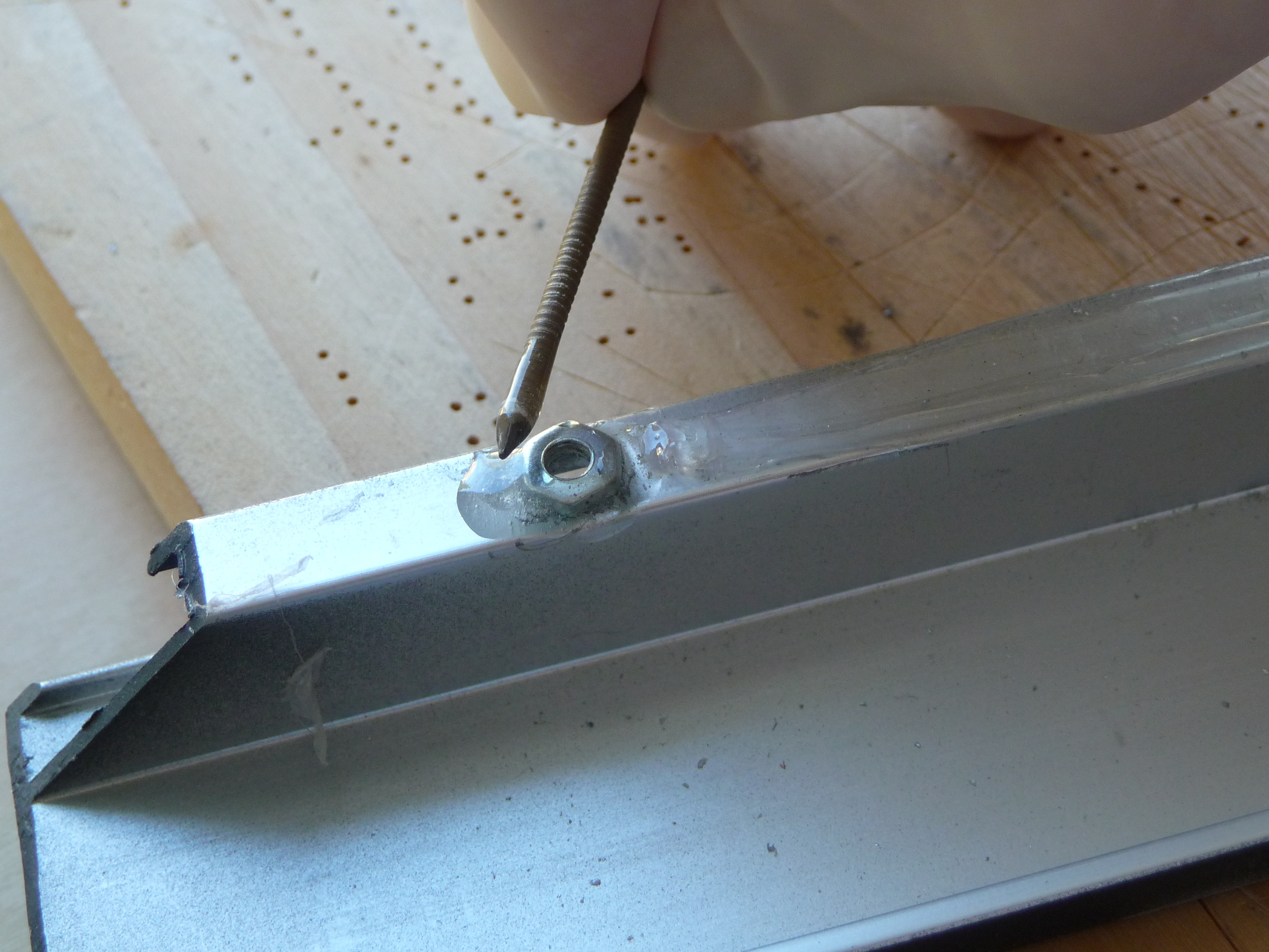
Assemble your frame and paint to your desired finish. The frame I used was originally unfinished so I primed the bare metal before spray-painting a flat black finish.
The Arduino PCB has the power supply so it needs to be mounted somewhere sturdy for when the barrel is inserted. I used the edge of the frame and epoxy resin to affix nuts through which the board could be attached.
You might also need to put down a layer of hot glue on the frame to act as an insulator between the bottom of the Arduino PCB and the frame – you could get some short circuits if the two come in contact.
Cut the back board
Using a utility knife, cut the back board to the size of your frame. Line up the power supply and cut the hole for the power supply. You can use a drill to mark the corners which will make things go a little smoother
For the buttons, mark and cut four square holes. It is mostly a matter of aesthetics as to where the buttons go, but be sure to check that the frame is clear of the PCB.
The button PCB might have some raised solder points. To make sure that the buttons are flush, you can scrape away some of the board.
The back board needs to be securely fastened to the frame. As the corners of my frame were steel, I was able to use a rare-earth magnet in each corner. I used hot glue to attach a small piece of metal to the board and quickly held it in place while the glue set.
Attach the acrylic front sheet to the frame

This step will vary somewhat based on the type of frame you have used. If you have used a regular picture frame you can probably skip this step altogether. I used rare-earth magnets to hold the front sheet to the frame.
Create a block of cardboard (I used leftovers from the light guide) to the appropriate height, leaving enough room for a magnet and a small piece of metal. The metal has to be large enough for a strong magnetic pull, but it also has to keep clear of the lettering. Since the front sheet is not that heavy you can probably get away with a piece about the same size as the magnet.
Glue the magnet to the cardboard block with hot glue. Next, place your piece of steel on the magnet. Place a dab of hot glue on the steel and quickly press your front sheet to the frame. After a few moments you can pull the front sheet away and the steel piece should now be in place.
Putting it all together
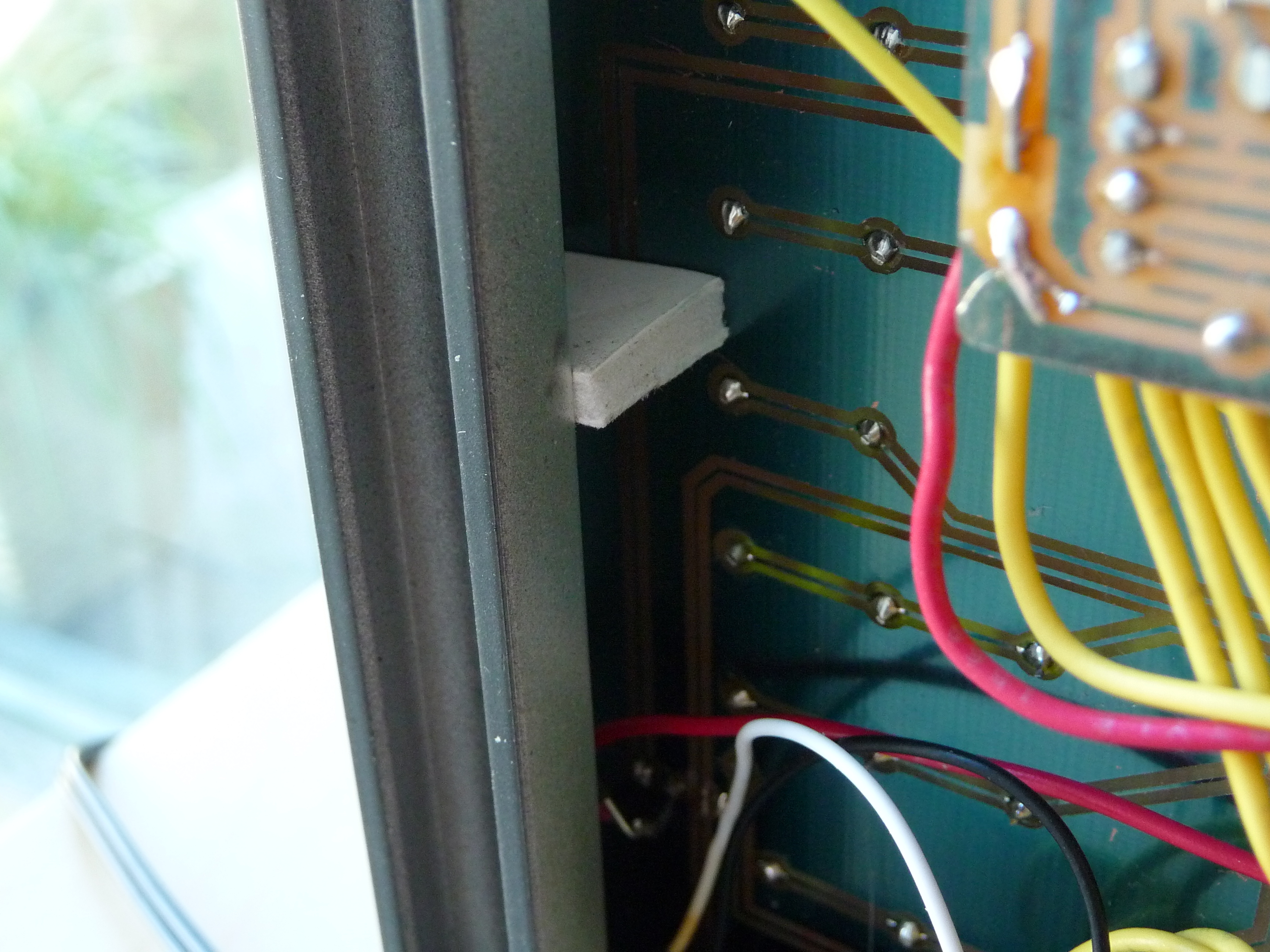

Begin by hooking up all your electrical connections (see the attached document for guidance) and insert the coin-cell battery in the holder.
Next, place the light guide/grid on the LED circuit board and slide everything into the frame.
Next screw down the Arduino PCB firmly in place.
You will probably need some sort of spacer to keep the LED PCB tight to the front of the frame. Cut a few small squares of foam-core board of cardboard just a bit larger than your gap. Slide these wedges into the space between the frame and the PCB and it should fit snugly.
The buttons can be hot-glued in place, using a piece of cardboard or foam-core board to build it up to the appropriate height.
Attach small plastic bumpers to the bottom of the frame to give it a sturdy base, snap on the front and back panels and the job is almost complete.
Light diffusion

You need to place a film of some sort between the LEDs and the acrylic front sheet. This will ensure that the letters light up from all angles in a smooth and even way.
I experimented with a few things but found a piece of cheap tracing paper works well. Cut a square of material a touch smaller than your front piece. No need to glue it in place as the magnets will do the job for you.
Clock operation


As soon as you plug in the power supply the clock will light up. You may see some lights flashing at first, but this is normal.
The clock has four buttons. Button 1 sets the hour, button 2 sets the minutes, button 3 cycles through the clock modes and button 4 changes the brightness.
The three clock modes are:
The default mode displays the time with each dot in the corner representing a minute increment. In the picture to the left, the time is 10:27.
The next mode displays the time with the corner dots advancing on each second
The next mode displays the seconds.