
![]()
From Wikipedia, the free encyclopedia

A simple flowchart representing a process for dealing with a non-functioning lamp.
A flowchart is a type of diagram that represents a workflow or process. A flowchart can also be defined as a diagrammatic representation of an algorithm, a step-by-step approach to solving a task.
The flowchart shows the steps as boxes of various kinds, and their order by connecting the boxes with arrows. This diagrammatic representation illustrates a solution model to a given problem. Flowcharts are used in analyzing, designing, documenting or managing a process or program in various fields.[1]
Overview[edit]
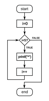
Flow diagram a C-style for loop, representing the following code:
for(i=0;i<5;i++)
  printf("*");
The loop will cause five asterisks to be printed.
Flowcharts are used to design and document simple processes or programs. Like other types of diagrams, they help visualize the process. Two of the many benefits are flaws and bottlenecks may become apparent. Flowcharts typically use the following main symbols:
- A process step, usually called an activity, is denoted as a rectangular box.
- A decision is usually denoted as a diamond.
A flowchart is described as «cross-functional» when the chart is divided into different vertical or horizontal parts, to describe the control of different organizational units. A symbol appearing in a particular part is within the control of that organizational unit. A cross-functional flowchart allows the author to correctly locate the responsibility for performing an action or making a decision, and to show the responsibility of each organizational unit for different parts of a single process.
Flowcharts represent certain aspects of processes and are usually complemented by other types of diagram. For instance, Kaoru Ishikawa defined the flowchart as one of the seven basic tools of quality control, next to the histogram, Pareto chart, check sheet, control chart, cause-and-effect diagram, and the scatter diagram. Similarly, in UML, a standard concept-modeling notation used in software development, the activity diagram, which is a type of flowchart, is just one of many different diagram types.
Nassi-Shneiderman diagrams and Drakon-charts are an alternative notation for process flow.
Common alternative names include: flow chart, process flowchart, functional flowchart, process map, process chart, functional process chart, business process model, process model, process flow diagram, work flow diagram, business flow diagram. The terms «flowchart» and «flow chart» are used interchangeably.
The underlying graph structure of a flowchart is a flow graph, which abstracts away node types, their contents and other ancillary information.
History[edit]
The first structured method for documenting process flow, the «flow process chart», was introduced by Frank and Lillian Gilbreth in the presentation «Process Charts: First Steps in Finding the One Best Way to do Work», to members of the American Society of Mechanical Engineers (ASME) in 1921.[2] The Gilbreths’ tools quickly found their way into industrial engineering curricula. In the early 1930s, an industrial engineer, Allan H. Mogensen began to train business people in the use of some of the tools of industrial engineering at his Work Simplification Conferences in Lake Placid, New York.
Art Spinanger, a 1944 graduate of Mogensen’s class, took the tools back to Procter and Gamble where he developed their Deliberate Methods Change Program. Ben S. Graham, another 1944 graduate, Director of Formcraft Engineering at Standard Register Industrial, applied the flow process chart to information processing with his development of the multi-flow process chart, to present multiple documents and their relationships.[3] In 1947, ASME adopted a symbol set derived from Gilbreth’s original work as the «ASME Standard: Operation and Flow Process Charts.»[4]
Douglas Hartree in 1949 explained that Herman Goldstine and John von Neumann had developed a flowchart (originally, diagram) to plan computer programs.[5] His contemporary account was endorsed by IBM engineers[6] and by Goldstine’s personal recollections.[7] The original programming flowcharts of Goldstine and von Neumann can be found in their unpublished report, «Planning and coding of problems for an electronic computing instrument, Part II, Volume 1» (1947), which is reproduced in von Neumann’s collected works.[8]
The flowchart became a popular tool for describing computer algorithms, but its popularity decreased in the 1970s, when interactive computer terminals and third-generation programming languages became common tools for computer programming, since algorithms can be expressed more concisely as source code in such languages. Often pseudo-code is used, which uses the common idioms of such languages without strictly adhering to the details of a particular one.
In the early 21st century, flowcharts were still used for describing computer algorithms.[9] Modern techniques such as UML activity diagrams and Drakon-charts can be considered to be extensions of the flowchart.
Types[edit]
Sterneckert (2003) suggested that flowcharts can be modeled from the perspective of different user groups (such as managers, system analysts and clerks), and that there are four general types:[10]
- Document flowcharts, showing controls over a document-flow through a system
- Data flowcharts, showing controls over a data-flow in a system
- System flowcharts, showing controls at a physical or resource level
- Program flowchart, showing the controls in a program within a system
Notice that every type of flowchart focuses on some kind of control, rather than on the particular flow itself.[10]
However, there are some different classifications. For example, Andrew Veronis (1978) named three basic types of flowcharts: the system flowchart, the general flowchart, and the detailed flowchart.[11] That same year Marilyn Bohl (1978) stated «in practice, two kinds of flowcharts are used in solution planning: system flowcharts and program flowcharts…».[12] More recently, Mark A. Fryman (2001) identified more differences: «Decision flowcharts, logic flowcharts, systems flowcharts, product flowcharts, and process flowcharts are just a few of the different types of flowcharts that are used in business and government».[13]
In addition, many diagram techniques are similar to flowcharts but carry a different name, such as UML activity diagrams.
Building blocks[edit]
Common symbols[edit]
The American National Standards Institute (ANSI) set standards for flowcharts and their symbols in the 1960s.[14] The International Organization for Standardization (ISO) adopted the ANSI symbols in 1970.[15] The current standard, ISO 5807, was revised in 1985.[16] Generally, flowcharts flow from top to bottom and left to right.[17]
| ANSI/ISO Shape | Name | Description |
|---|---|---|
| Flowline (Arrowhead)[15] | Shows the process’s order of operation. A line coming from one symbol and pointing at another.[14] Arrowheads are added if the flow is not the standard top-to-bottom, left-to right.[15] | |

|
Terminal[14] | Indicates the beginning and ending of a program or sub-process. Represented as a stadium,[14] oval or rounded (fillet) rectangle. They usually contain the word «Start» or «End», or another phrase signaling the start or end of a process, such as «submit inquiry» or «receive product». |

|
Process[15] | Represents a set of operations that changes value, form, or location of data. Represented as a rectangle.[15] |

|
Decision[15] | Shows a conditional operation that determines which one of the two paths the program will take.[14] The operation is commonly a yes/no question or true/false test. Represented as a diamond (rhombus).[15] |

|
Input/Output[15] | Indicates the process of inputting and outputting data,[15] as in entering data or displaying results. Represented as a rhomboid.[14] |

|
Annotation[14] (Comment)[15] | Indicating additional information about a step in the program. Represented as an open rectangle with a dashed or solid line connecting it to the corresponding symbol in the flowchart.[15] |

|
Predefined Process[14] | Shows named process which is defined elsewhere. Represented as a rectangle with double-struck vertical edges.[14] |

|
On-page Connector[14] | Pairs of labeled connectors replace long or confusing lines on a flowchart page. Represented by a small circle with a letter inside.[14][18] |
| Off-page Connector[14] | A labeled connector for use when the target is on another page. Represented as a home plate-shaped pentagon.[14][18] |
Other symbols[edit]
The ANSI/ISO standards include symbols beyond the basic shapes. Some are:[17][18]
| Shape | Name | Description |
|---|---|---|

|
Data File or Database | Data represented by a cylinder symbolizing a disk drive. |
| Document | Single documents represented as a rectangle with a wavy base. | |
| Multiple documents represented as a stack of rectangles with wavy bases. | ||
| Manual operation | Represented by a trapezoid with the longest parallel side at the top, to represent an operation or adjustment to process that can only be made manually. | |
| Manual input | Represented by quadrilateral, with the top irregularly sloping up from left to right, like the side view of a keyboard. | |
| Preparation or Initialization | Represented by an elongated hexagon, originally used for steps like setting a switch or initializing a routine. |
Parallel processing[edit]
- Parallel Mode is represented by two horizontal lines at the beginning or ending of simultaneous operations[17]
For parallel and concurrent processing the Parallel Mode horizontal lines[19] or a horizontal bar[20] indicate the start or end of a section of processes that can be done independently:
- At a fork, the process creates one or more additional processes, indicated by a bar with one incoming path and two or more outgoing paths.
- At a join, two or more processes continue as a single process, indicated by a bar with several incoming paths and one outgoing path. All processes must complete before the single process continues.[20]
Software[edit]
Diagramming[edit]
Any drawing program can be used to create flowchart diagrams, but these will have no underlying data model to share data with databases or other programs such as project management systems or spreadsheet. Many software packages exist that can create flowcharts automatically, either directly from a programming language source code, or from a flowchart description language.
There are several applications and visual programming languages[21] that use flowcharts to represent and execute programs. Generally these are used as teaching tools for beginner students.
See also[edit]
[edit]
|
[edit]
|
References[edit]
- ^ SEVOCAB: Software Systems Engineering Vocabulary. Term: Flow chart. Retrieved 31 July 2008.
- ^ Frank Bunker Gilbreth, Lillian Moller Gilbreth (1921) «Process Charts» (PDF). Archived from the original on 2015-05-09. Retrieved 2016-05-06.
{{cite web}}: CS1 maint: bot: original URL status unknown (link). American Society of Mechanical Engineers. - ^ Graham, Ben S. Jr. (10 June 1996). «People come first». Keynote Address at Workflow Canada.
- ^ American Society of Mechanical Engineers (1947) ASME standard; operation and flow process charts. New York, 1947. (online version)
- ^ Hartree, Douglas (1949). Calculating Instruments and Machines. The University of Illinois Press. p. 112.
- ^ Bashe, Charles (1986). IBM’s Early Computers. The MIT Press. p. 327. ISBN 9780262022255.
- ^ Goldstine, Herman (1972). The Computer from Pascal to Von Neumann. Princeton University Press. pp. 266–267. ISBN 0-691-08104-2.
- ^ Taub, Abraham (1963). John von Neumann Collected Works. Vol. 5. Macmillan. pp. 80–151.
- ^ Bohl, Rynn: «Tools for Structured and Object-Oriented Design», Prentice Hall, 2007.
- ^ a b Alan B. Sterneckert (2003) Critical Incident Management. p. 126
- ^ Andrew Veronis (1978) Microprocessors: Design and Applications. p. 111
- ^ Marilyn Bohl (1978) A Guide for Programmers. p. 65.
- ^ Mark A. Fryman (2001) Quality and Process Improvement. p. 169.
- ^ a b c d e f g h i j k l m Gary B. Shelly; Misty E. Vermaat (2011). Discovering Computers, Complete: Your Interactive Guide to the Digital World. Cengage Learning. pp. 691–693. ISBN 978-1-111-53032-7.
- ^ a b c d e f g h i j k Harley R. Myler (1998). «2.3 Flowcharts». Fundamentals of Engineering Programming with C and Fortran. Cambridge University Press. pp. 32–36. ISBN 978-0-521-62950-8.
- ^ «ISO 5807:1985». International Organization for Standardization. February 1985. Retrieved 23 July 2017.
- ^ a b c Flowcharting Techniques GC20-8152-1. IBM. March 1970. p. 10.
- ^ a b c «What do the different flowchart shapes mean?». RFF Electronics. Retrieved 23 July 2017.
- ^ Jonathan W. Valvano (2011). Embedded Microcomputer Systems: Real Time Interfacing. Cengage Learning. pp. 131–132. ISBN 978-1-111-42625-5.
- ^ a b Robbie T. Nakatsu (2009). Reasoning with Diagrams: Decision-Making and Problem-Solving with Diagrams. John Wiley & Sons. pp. 68–69. ISBN 978-0-470-40072-2.
- ^ Myers, Brad A. «Visual programming, programming by example, and program visualization: a taxonomy.» ACM SIGCHI Bulletin. Vol. 17. No. 4. ACM, 1986.
Further reading[edit]
- ISO 5807 (1985). Information processing – Documentation symbols and conventions for data, program and system flowcharts, program network charts and system resources charts. International Organization for Standardization.
- ISO 10628: Diagrams for the chemical and petrochemical industry
- ECMA 4: Flowcharts (withdrawn – list of withdrawn standards)
- Schultheiss, Louis A., and Edward M. Heiliger. «Techniques of flow-charting.» (1963); with introduction by Edward Heiliger.
External links[edit]
![]()
Wikimedia Commons has media related to Flow chart.
- Flowcharting Techniques: An IBM manual from 1969 (5 MB; PDF)
Are you wondering how to make the best flowchart ever? You’ve come to the right place. Fasten your seatbelts and be ready to travel to the world of laconic and clear flowcharts. When we finish, you’ll be ready to create your greatest flow sheet.
What is a Flowchart?
A flowchart is a graphical representation of business processes designed to explain complex things in simple words. Its essence is reflected in the name — chart of a flow.
Long story short, it’s a diagram made of forms and symbols that depict a process or algorithm. These forms are connected with arrows to show the direction of process flow.
Flowcharts are used to plan, document, study, communicate. Complex processes are depicted as clear and simple diagrams. Everyone can understand the message.

General Flowchart Symbols
- The Oval means a beginning or an end. That’s why it’s also called ‘terminator’. Start and end your flowchart with this shape.
- The Rectangle is one step of the process and the most frequently-used shape. Every step in the business process depicted should be represented with it.
- The Arrow indicates directions. It connects flowchart parts and helps to tell the whole story: exposition, climax, and resolution.
- The Diamond means a decision. Be it a binary, one-of-three or even complex decision, it has its own subsequent story.
Also, besides these basic symbols, there are special ones:
- Document symbols
- Data symbols
- Input and output symbols
- Merging and connecting
- Other shapes


Once you know the shapes’ roles, start creating your professionally-designed flow-sheet! First, follow these basic principles:
- Create a list of core concepts. They should be intuitive and clear. The steps of the process should be simple and easy to understand. The success of any flowchart is in its readability.
- Choose the format. It can be standard and swimlane. The first one is suitable for simple processes with only the main concepts and possible actions. The latter fits process works performed by several teams. So, every team takes its ‘swimlane’.
- Define a set of symbols to use. That may be your company standard.
- Start with an oval terminator box. Think about what goes next and add arrows to describe the flow.
- Divide complex processes into parts. Too dense illustrations might be impossible to read. Separate sub processes into another chart. Add a link to a new one while designing your digital flowchart.
- Finally, share the scheme with others. Make sure it is used as a formal system by other teammates.

Creating a Flowchart with Word
The first popular way to manage our today’s main task is the most well-known text processor. Here are the main steps:
- Create a canvas. From the ‘Insert’ tab, go to the ‘Shapes’ menu, and select ‘New Drawing Canvas’.
- Click on your canvas to activate the grid. Set it in the ‘Format’ tab by clicking ‘Align’ and ‘Grid Settings’.
- Add and connect shapes. Return to the ‘Insert’ tab and proceed to ‘Shapes’. Format blocks in the self-titled tab. If you select an arrow, start near the first shape, drag and drop it.
- Add text and comments. Just start typing on the shape of your choice. Edit the text format via the tools panel.
Disadvantages:
- Word is primarily a text processor, so creating a flow diagram can be quite challenging.
- If you are not an advanced Word user, the process may take you more than several hours.
How to Do a Flowchart with Excel
The whole process is very similar to the previous one.
- Set a grid. Select all cells on your spreadsheet. Select ‘Column Width’ from the right-click menu and set it as ‘2.14’. All cells will become square.
- Line up margins. This is necessary only for exporting your flowchart to other apps, e.g. MS Word. In the ‘Layout’ tab, select ‘Margins’.
- Add and connect shapes. In the ‘Insert’ tab, click ‘Shapes’. Add blocks you need and format them in the ‘Format’ tab.
- Add text and comments. Just click on the cell you want to fill with text. Be concise and brief.
Disadvantages:
- The complexity of the process. People consider Excel even more difficult to use than Word!
- It’s a long process, so some people prefer buying templates for Excel. Still, they may cost not even fifty dollars!

Create a Flowchart with Powerpoint
Since MS Office is a holistic tool, the actions are very similar to the previous point.
- Set a grid. Go to ‘View’ > ‘Show’ and check the ‘Gridlines’ box.
- Add shapes. Visit the ‘Insert’ tab, select ‘Illustrations’ > ‘Shapes’. Note, there are special ‘Lines’ and ‘Flowchart’ sections. Connect different shapes with lines. Edit their format in the main toolbar.
- Type texts. Click on the shape and start typing. Add comments to the lines if necessary.
Disadvantages:
- Though this tool is more comfortable than previous ones, creating a chart may take the whole day.
Creating a Flowchart with Google Docs
If you like Google’s Office Suite more than MS Office, here is a short manual for you!
- Create a file for your flowchart. Once you’ve opened a Docs file, select ‘Insert’ > ‘Drawing’ > ‘New’.
- Add shapes. From the ‘Drawing’ tab, click the icon with a circle and a square in it. Proceed to ‘Shapes’ and select the one you need.
- Connect them. Choose the line tool (the icon with an arrow in it) and draw a line.
- Format shapes and lines. To change their design, select a shape or line, click on ‘Fill Color’.
- Add your flowchart to the document. Once your chart is ready, clicking on ‘Save and close’. It will appear in your Google Document.
Disadvantages:
- The long and complex process for those who have never created flowcharts before.

Step-by-Step Creating a Flowchart with FlowMapp
Using a flowchart software is the best solution for people who are aimed at getting the fastest and best results. FlowMapp is tailored especially to the needs of both professionals and amateurs who want to save time and increase productivity.
With our app, you can easily create:
- Sitemaps
- User flows
- Personas
- Customer journey maps (CJM)
Let’s start creating, for example, a user flow
1. First, you must be registered in the system. It’s free and takes around a minute.
2. Once you are signed in, select what you need. Next, click on the icon with a plus on it.

3. Name your project and click on the blue button.

4. In the center of the new screen, click on the icon with a plus on it. It will turn from white to blue after you hover over it.
![]()
5. A toolbar with shapes, text, images and other features will appear. Select the first shape and start creating your flowchart!

6. Add as many elements as you need to convey the sense of your business process.

By the way, you can move your shapes on the page — select one of them by clicking on the shape or select all by clicking near all your shapes or using ‘Shift’+left mouse click.

7. For more convenience, you can add a background grid or add a colored background.

8. To change the format of shapes, use the menu at the bottom of the screen. It appears once you click on the shape.

9. To connect the shapes, hover over the first one, click on the dot aside the shape, drag it to the next shape, then drop it. Thus, an arrow will be transformed automatically.
![]()
Click on it to edit its style from the toolbar at the bottom.

10. To make your flowchart more intuitive, add icons to the texts on your shapes. To make it more informative, add catalogs, sitemaps, customer journeys.
![]()
You now see that drawing digital flow schemes doesn’t need any professional knowledge if you use the right tool. Intuitive interface, user-friendly tips and a bit of your time are everything you need!
Flowchart Examples
Explore the examples of flowcharts done in FlowMapp. The good news is that a brilliant design does not require long days of hard work!
Here is the flowchart depicting onboarding and sign in/sign up user flows for mobile deals app:

This is an informative yet easy to understand user searching journey:

In this flowchart, you’ll find gamification and user experience business scheme:

Advantages of Flowchart Creating in FlowMapp
- Professional results. Your design will be more advanced than if you made it in Word or Excel.
- Simplicity. Everyone can do this, even without special skills and previous experience.
- Variety of tools. Create user flowcharts, personas, CJMs, and sitemaps. You can use all of them at once by integrating one into another.
- Intuitive customizing. Design blocks, format text, add images, and enjoy effortless formatting via intuitive pop-up panel tools.
- Icon library. A handful of free icons will make your concept more clear and obvious.
- Endless working space for many user flows. Enjoy literally endless space and add as many flowcharts, sitemaps, CJMs as you need.
- Export and sharing opportunities. Share in the web format, export in an image, PDF or SVG.
- Collaboration. Work on your project with the entire team!

7 Bonus Tips: Best Practices of Drawing Effective Flowcharts
- Use standard symbols, if you want to share your scheme. It should be understood by everyone who looks at it.
- Be careful with colors and sizes. Don’t “overdesign” your flow diagram. This saturates the scheme with informational noise.
- Set a unified spacing value. Stick to the middle ground when choosing spacing between shapes.
- Keep all data on one page. Shorten your flowchart or divide it into parts, if it’s too large.
- Use the ‘Right to Left’ flow, not ‘Left to Right’. People read like this, so they will perceive the data quicker and more intuitively.
- Use a ‘Split path’, not a ‘Decision’. Though we have a Diamond symbol, people find a ‘Split path’ (a rectangle with two arrows) easier to understand.
- Return lines should be placed under your flowchart. Some people place it above their diagrams, but this can be distracting.
The Bottom Line
Congrats! You now know basically everything to start creating your perfect process flowchart!
- Think out the concept you want to depict.
- Choose the tool from what we’ve reviewed.
- Start creating your chart using our manual from this article!


Feel free to ask questions in the comments or to address our support team if you need some help!
- flowchart
-
- рабочая диаграмма
- блок-схема
блок-схема
—
[http://www.iks-media.ru/glossary/index.html?glossid=2400324]блок-схема
—
[Лугинский Я. Н. и др. Англо-русский словарь по электротехнике и электроэнергетике. 2-е издание — М.: РУССО, 1995 — 616 с.]блок-схема
Условное изображение алгоритма, программы для ЭВМ, процесса принятия решения, документооборота и т.п., предназначенное для выявления их структуры и общей последовательности операций. Пример Б.-с. см. в статье Алгоритм. Б.с. бывают принципиальные (укрупненные, отражающие общую логику процесса) и рабочие, детальные.
[http://slovar-lopatnikov.ru/]Тематики
- экономика
- электросвязь, основные понятия
- электротехника, основные понятия
EN
- block diagram
- flowchart
рабочая диаграмма
графическая схема программы
блок-схема
—
[Л.Г.Суменко. Англо-русский словарь по информационным технологиям. М.: ГП ЦНИИС, 2003.]Тематики
- информационные технологии в целом
Синонимы
- графическая схема программы
- блок-схема
EN
- flowchart
Англо-русский словарь нормативно-технической терминологии.
.
2015.
Смотреть что такое «flowchart» в других словарях:
-
flowchart — ☆ flowchart [flōchärt΄ ] n. a diagram, often using geometric symbols, showing steps in a sequence of operations, as in manufacturing or in a computer program * * * flow chart also flow·chart (flōʹchärt ) n. A schematic representation of a… … Universalium
-
flowchart — [n] sequential diagram flow diagram, flow sheet; concepts 625,660 … New thesaurus
-
flowchart — ☆ flowchart [flōchärt΄ ] n. a diagram, often using geometric symbols, showing steps in a sequence of operations, as in manufacturing or in a computer program … English World dictionary
-
Flowchart — A flowchart is a schematic representation of an algorithm or a stepwise process, showing the steps as boxes of various kinds, and their order by connecting these with arrows. Flowcharts are used in designing or documenting a process or program.… … Wikipedia
-
Flowchart — Flow|chart , das; s, s [engl. flow chart, aus: flow = das Fließen, der Fluss u. chart, ↑ Chart (1)] (EDV): engl. Bez. für: Flussdiagramm. * * * Flowchart [dt. »Flussdiagramm«], Programmablaufplan … Universal-Lexikon
-
flowchart — /ˈfloʊtʃat/ (say flohchaht) verb (t) to provide a flow chart for: to flowchart the work processes. –flowcharting, noun …
-
flowchart — struktūrinė schema statusas T sritis automatika atitikmenys: angl. block diagram; block scheme; flow diagram; flowchart; structure diagram vok. Blockschaltbild, n; Blockschema, n; Strukturschema, n rus. структурная схема, f pranc. ordinogramme,… … Automatikos terminų žodynas
-
flowchart — noun Date: 1920 a diagram that shows step by step progression through a procedure or system especially using connecting lines and a set of conventional symbols • flowcharting noun … New Collegiate Dictionary
-
Flowchart — Flussdiagramm steht für ein Ablaufdiagramm eine in der Informatik verwendete Darstellungsform von Ablaufplänen in Computerprogrammen, siehe Programmablaufplan eine in der strukturierten Analyse verwendete Darstellungsform der Verarbeitung von… … Deutsch Wikipedia
-
Flowchart — Organigramme de programmation Un organigramme de programmation (parfois appelé algorigramme ou ordinogramme) est une représentation graphique normalisée de l enchaînement des opérations et des décisions effectuées par un programme d ordinateur.… … Wikipédia en Français
-
Flowchart — … Википедия
Flowcharts are nothing but the graphical representation of the data or the algorithm for a better understanding of the code visually. It displays step-by-step solutions to a problem, algorithm, or process. It is a pictorial way of representing steps that are preferred by most beginner-level programmers to understand algorithms of computer science, thus it contributes to troubleshooting the issues in the algorithm. A flowchart is a picture of boxes that indicates the process flow in a sequential manner. Since a flowchart is a pictorial representation of a process or algorithm, it’s easy to interpret and understand the process. To draw a flowchart, certain rules need to be followed which are followed by all professionals to draw a flowchart and is widely accepted all over the countries.
Use of a flowchart
Following are the uses of a flowchart:
- It is a pictorial representation of an algorithm that increases the readability of the program.
- Complex programs can be drawn in a simple way using a flowchart.
- It helps team members get an insight into the process and use this knowledge to collect data, detect problems, develop software, etc.
- A flowchart is a basic step for designing a new process or add extra features.
- Communication with other people becomes easy by drawing flowcharts and sharing them.
When to use flowchart
Flowcharts are mainly used in the below scenarios:
- It is most importantly used when the programmers make projects. As a flowchart is a basic step to make the design of projects pictorially, it is preferred by many.
- When the flowcharts of a process are drawn, the programmer understands the non-useful parts of the process. So flowcharts are used to separate useful logic from the unwanted parts.
- Since the rules and procedure of drawing a flowchart are universal, flowchart serves as a communication channel to the people who are working on the same project for better understanding.
- Optimizing a process becomes easier with flowcharts. The efficiency of code is improved with the flowchart drawing.
Types of Flowcharts
Three types of flowcharts are listed below:
- Process flowchart: This type of flowchart shows all the activities that are involved in making a product. It basically provides a pathway to analyze the product to be built. A process flowchart is most commonly used in process engineering to illustrate the relation between the major as well as minor components present in the product. It is used in business product modeling to help understand employees about the project requirements and gain some insight about the project.
- Data flowchart: As the name suggests, the data flowchart is used to analyze the data, specifically it helps in analyzing the structural details related to the project. Using this flowchart, one can easily understand the data inflow and outflow from the system. It is most commonly used to manage data or to analyze information to and fro from the system.
- Business Process Modeling Diagram: Using this flowchart or diagram, one can analytically represent the business process and help simplify the concepts needed to understand business activities and the flow of information. This flowchart illustrates the business process and models graphically which paves a way for process improvement.
Types of boxes used to make a flowchart
There are different types of boxes that are used to make flowcharts. All the different kinds of boxes are connected to one another by arrow lines. Arrow lines is used to display the flow of control. Let’s learn about each box in detail.
1. Terminal

This box is of an oval shape which is used to indicate the start or end of the program. Every flowchart diagram has this oval shape that depicts the start of an algorithm and another oval shape that depicts the end of an algorithm. For example:

2. Data

This is a parallelogram-shaped box inside which the inputs or outputs are written. This basically depicts the information that is entering the system or algorithm and the information that is leaving the system or algorithm. For example: if the user wants to input a from the user and display it, the flowchart for this would be:

3. Process

This is a rectangular box inside which a programmer writes the main course of action of the algorithm or the main logic of the program. This is the crux of the flowchart as the main processing codes is written inside this box. For example: if the programmer wants to add 1 to the input given by the user, he/she would make the following flowchart:

4. Decision

This is a rhombus-shaped box, control statements like if, or condition like a > 0, etc are written inside this box. There are 2 paths from this one which is “yes” and the other one is “no”. Like every decision has either yes or no as an option, similarly, this box to have these as options. For example: if the user wants to add 1 to an even number and subtract 1 if the number is odd, the flowchart would be:

5. Flow

This arrow line represents the flow of the algorithm or process. It represents the direction of the process flow. in all the previous examples, we included arrows in every step to display the flow of the program. arrow increases the readability of the program.
6. On-Page Reference

This circular figure is used to depict that the flowchart is in continuation with the further steps. This figure comes into use when the space is less and the flowchart is long. Any numerical symbol is present inside this circle and that same numerical symbol will be depicted before the continuation to make the user understand the continuation. Below is a simple example depicting the use of On-Page Reference

Advantages of Flowchart
- It is the most efficient way of communicating the logic of system.
- It act like a guide for blueprint during program designed.
- It also helps in debugging process.
- Using flowchart we can easily analyze the programs.
- flowcharts are good for documentation.
Disadvantages of Flowchart
- Flowcharts are difficult to draw for large and complex programs.
- It does not contain the proper amount of details.
- Flowcharts are very difficult to reproduce.
- Flowcharts are very difficult to modify.
Sample Problems
Question 1. Draw a flowchart to find the greatest number among the 2 numbers.
Solution:
Algorithm:
1. Start
2. Input 2 variables from user
3. Now check the condition If a > b, goto step 4, else goto step 5.
4. Print a is greater, goto step 6
5. Print b is greater
6. Stop
FlowChart:

Question 2. Draw a flowchart to check whether the input number is odd or even
Solution:
Algorithm:
1. Start
2. Put input a
3. Now check the condition if a % 2 == 0, goto step 5. Else goto step 4
4. Now print(“number is odd”) and goto step 6
5. Print(“number is even”)
6. Stop
FlowChart:

Question 3. Draw a flowchart to print the input number 5 times.
Solution:
Algorithm:
1. Start
2. Input number a
3. Now initialise c = 1
4. Now we check the condition if c <= 5, goto step 5 else, goto step 7.
5. Print a
6. c = c + 1 and goto step 4
7. Stop
FlowChart:

Question 4. Draw a flowchart to print numbers from 1 to 10.
Solution:
Algorithm:
1. Start
2. Now initialise c = 1
3. Now we check the condition if c < 11, then goto step 4 otherwise goto step 6.
4. Print c
5. c = c + 1 then goto step 3
6. Stop
FlowChart:

Question 5. Draw a flowchart to print the first 5 multiples of 3.
Solution:
Algorithm:
1. Start
2. Now initialise c = 1
3. Now check the condition if c < 6, then goto step 4. Otherwise goto step 6
4. Print 3 * c
5. c += 1. Then goto step 3.
6. Stop
FlowChart:
