
Last Updated on: July 22nd, 2022
This article is a continuation of the Series on Linux Device Drivers and carries the discussion on Linux device drivers and their implementation. The aim of this series is to provide easy and practical examples that anyone can understand. This is the I2C Linux Device Driver using Raspberry PI – Linux Device Driver Tutorial Part 37.
We are using the Raspberry PI 4 Model B for this demonstration.
You can also read BMP280 Bosch Pressure Sensor I2C Device Driver, I2C dummy bus driver, I2C bus driver, SSD1306 driver, and GPIO Linux Driver.
Prerequisites
- I2C Introduction – Part 1 (Basics)
- I2C Introduction – Part 2 (Advanced Topics)
Hardware Required
- Raspberry Pi
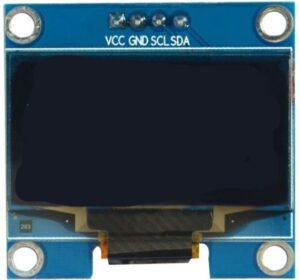
- SSD1306 OLED I2C Display
Bring up Raspberry PI
- Install Raspberry Pi OS (32-bit) with desktop in the SD card.
- Then install the kernel header using
sudo apt install raspberrypi-kernel-headers
For your information, In our Raspberry PI 4 board, kernel 5.4.51-v7l+ is installed.
Please enable the I2C in the Raspberry Pi.
I2C
I assume that you know about the I2C and how the master and slave are communicating normally. If you don’t know about I2C, please go through the I2C’s part 1 and part 2 tutorials before beginning. In this tutorial, we will focus on how the Linux kernel is handling the I2C.
I2C Subsystem
The kernel divided the I2C subsystem by Buses and Devices. The Buses are again divided into Algorithms and Adapters. The devices are again divided into Drivers and Clients. The below image will give you some understandings.
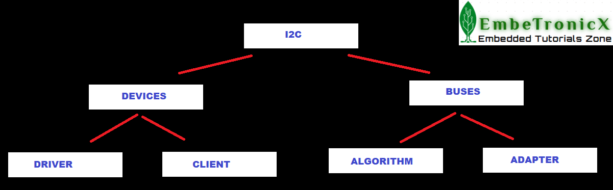
Algorithm
An Algorithm driver contains a general code that can be used for a whole class of I2C adapters.
Adapters
An Adapter effectively represents a bus – it is used to tie up a particular I2C with an algorithm and bus number. Each specific adapter driver either depends on one algorithm driver or includes its own implementation.
Clients
A Client represents a chip (slave) on the I2C.
Drivers
This is the driver that we are writing for the client.
Usually, Driver and Client are more closely integrated than Algorithm and Adapter.
So, you will need a driver for your I2C bus, and drivers for your I2C devices (usually one driver for each device).
I2C Driver in Linux Kernel
Steps that involve while writing the I2C device driver are given below.
- Get the I2C adapter.
- Create the
oled_i2c_board_infostructure and create a device using that. - Create the
i2c_device_idfor your slave device and register that. - Create the
i2c_driverstructure and add that to the I2C subsystem. - Now the driver is ready. So you can transfer the data between master and slave.
- Once you are done, then remove the device.
Get the I2C adapter
In raspberry Pi 4, the i2c-1 bus is available already. You can check that using the command ls -al /sys/bus/i2c/devices/. So we will use the below API to get the adapter structure of this I2C bus.
struct i2c_adapter *i2c_get_adapter(int nr);
Where,
nr – I2C bus number. In our case (Raspberry Pi 4), it should be 1.
It returns the struct i2c_adapter.
Create the board info
Once you get the adapter structure, then create the board info and using that board info, create the device.
Create Board info
Just create the i2c_board_info structure and assign required members of that.
struct i2c_board_info {
  char type[I2C_NAME_SIZE];
  unsigned short flags;
  unsigned short addr;
  void * platform_data;
  struct dev_archdata * archdata;
  struct device_node * of_node;
  struct fwnode_handle * fwnode;
  int irq;
};
where,
type[I2C_NAME_SIZE] – chip type, to initialize i2c_client.name
flags – to initialize i2c_client.flags
addr – stored in i2c_client.addr
platform_data – stored in i2c_client.dev.platform_data
archdata – copied into i2c_client.dev.archdata
of_node – pointer to OpenFirmware device node
fwnode – device node supplied by the platform firmware
irq – stored in i2c_client.irq
You can use I2C_BOARD_INFO macro to initialize the essential fields of struct i2c_board_info.
I2C_BOARD_INFO ( dev_type, dev_addr);
where,
dev_type – identifies the device type
dev_addr – the device’s address on the bus
Create Device
Now board info structure is ready. Let’s instantiate the device from that I2C bus.
struct i2c_client * i2c_new_device ( struct i2c_adapter * adap, struct i2c_board_info const * info);
where,
*adap – Adapter structure that we got from i2c_get_adapter()
*info – Board info structure that we have created
This will return the i2c_client structure. We can use this client for our future transfers.
Note: If you are using the newer kernel (5.2 =<), then you must use the i2c_new_client_device API instead of i2c_new_device.
Now we will see the example for this section. So that you will get some idea that how we are using this in our code.
Example
#define I2C_BUS_AVAILABLE   (          1 )              // I2C Bus available in our Raspberry Pi
#define SLAVE_DEVICE_NAME   ( "ETX_OLED" )              // Device and Driver Name
#define SSD1306_SLAVE_ADDR  (       0x3C )              // SSD1306 OLED Slave Address

static struct i2c_adapter *etx_i2c_adapter     = NULL;  // I2C Adapter Structure
static struct i2c_client  *etx_i2c_client_oled = NULL;  // I2C Cient Structure (In our case it is OLED)

/*
** I2C Board Info strucutre
*/
static struct i2c_board_info oled_i2c_board_info = {
        I2C_BOARD_INFO(SLAVE_DEVICE_NAME, SSD1306_SLAVE_ADDR)
    };

/*
** Module Init function
*/
static int __init etx_driver_init(void)
{
    ....

    etx_i2c_adapter     = i2c_get_adapter(I2C_BUS_AVAILABLE);
    etx_i2c_client_oled = i2c_new_device(etx_i2c_adapter, &oled_i2c_board_info);

    ....
    return 0;
}
Create the device id and register
Now we have to create the i2c driver for our slave. In order to do that, you have to create the device id and i2c_driver. Then add that driver to the I2C subsystem.
Create the device id
Just create the structure i2c_device_id and initialize the necessary members.
struct i2c_device_id {
  char name[I2C_NAME_SIZE];
  kernel_ulong_t driver_data;
};
where,
name – Slave name
driver_data – Data private to the driver (This data will be passed to the respective driver)
After this, call MODULE_DEVICE_TABLE(i2c, my_id_table) in order to expose the driver along with its I2C device table IDs to userspace.
Create the i2c_driver
struct i2c_driver {
  unsigned int class;
  int (* attach_adapter) (struct i2c_adapter *);
  int (* probe) (struct i2c_client *, const struct i2c_device_id *);
  int (* remove) (struct i2c_client *);
  void (* shutdown) (struct i2c_client *);
  void (* alert) (struct i2c_client *, unsigned int data);
  int (* command) (struct i2c_client *client, unsigned int cmd, void *arg);
  struct device_driver driver;
  const struct i2c_device_id * id_table;
  int (* detect) (struct i2c_client *, struct i2c_board_info *);
  const unsigned short * address_list;
  struct list_head clients;
};
Where,
class – What kind of i2c device we instantiate (for detect)
attach_adapter – Callback for bus addition (deprecated)
probe – Callback for device binding
remove – Callback for device unbinding
shutdown – Callback for device shutdown
alert – Alert callback, for example for the SMBus alert protocol
command – Callback for bus-wide signaling (optional)
driver – Device driver model driver
id_table – List of I2C devices supported by this driver
detect – Callback for device detection
address_list – The I2C addresses to probe (for detect)
clients – List of detected clients we created (for i2c-core use only)
Add the I2C driver to the I2C subsystem
Now we have the i2c_driver structure. So we can add this structure to the I2C subsystem using the below API.
i2c_add_driver(struct i2c_driver *i2c_drive);
Where,
i2c_drive – The i2c_driver structure that we have created.
During the call to i2c_add_driver to register the I2C driver, all the I2C devices will be traversed. Once matched, the probe function of the driver will be executed.
You can remove the driver using i2c_del_driver(struct i2c_driver *i2c_drive).
Let’s put this together and the code snippet is shown below.
Example
/*
** This function getting called when the slave has been found
** Note : This will be called only once when we load the driver.
*/
static int etx_oled_probe(struct i2c_client *client,
                         const struct i2c_device_id *id)
{
    ...

    return 0;
}

/*
** This function getting called when the slave has been removed
** Note : This will be called only once when we unload the driver.
*/
static int etx_oled_remove(struct i2c_client *client)
{
    ...
    return 0;
}

/*
** Structure that has slave device id
*/
static const struct i2c_device_id etx_oled_id[] = {
        { SLAVE_DEVICE_NAME, 0 },
        { }
};
MODULE_DEVICE_TABLE(i2c, etx_oled_id);

/*
** I2C driver Structure that has to be added to linux
*/
static struct i2c_driver etx_oled_driver = {
        .driver = {
            .name   = SLAVE_DEVICE_NAME,
            .owner  = THIS_MODULE,
        },
        .probe          = etx_oled_probe,
        .remove         = etx_oled_remove,
        .id_table       = etx_oled_id,
};

/*
** Module Init function
*/
static int __init etx_driver_init(void)
{
    ...
    i2c_add_driver(&etx_oled_driver);
    ...
    return 0;
}
Transfer data
Till this point, everything is on our plate. So, we can start the communication between master and slave. I meant data transfer.
Send data
i2c_master_send
This API issue a single I2C message in the master transmit mode.
int i2c_master_send ( const struct i2c_client * client, const char * buf, int count);
Where,
client – Handle to the slave device
buf – Data that will be written to the slave
count – How many bytes to write, must be less than 64k since msg length is u16
It returns negative errno, or else the number of bytes written.
i2c_smbus_write_byte
This API is used to send one byte to the slave.
s32 i2c_smbus_write_byte ( const struct i2c_client * client, u8 value);
Where,
client – Handle to the slave device
value – Byte to be sent
It returning negative errno else zero on success.
i2c_smbus_write_byte_data
s32 i2c_smbus_write_byte_data ( const struct i2c_client * client, u8 command, u8 value);
Where,
client – Handle to the slave device
command – Byte interpreted by slave
value – Byte being written
It returning negative errno else zero on success.
i2c_smbus_write_word_data
s32 i2c_smbus_write_word_data ( const struct i2c_client * client, u8 command, u16 value);
Where,
client – Handle to the slave device
command – Byte interpreted by slave
value – 16-bit “word” being written
It returning negative errno else zero on success.
i2c_smbus_write_block_data
s32 i2c_smbus_write_block_data ( const struct i2c_client * client, u8 command, u8 length, const u8 * values);
Where,
client – Handle to the slave device
command – Byte interpreted by slave
length – Size of the data block; SMBus allows at most 32 bytes
values – Byte array which will be written
It returns negative errno else zero on success.
Read data
i2c_master_recv
This API issue a single I2C message in master receive mode.
int i2c_master_recv ( const struct i2c_client * client, const char * buf, int count);
Where,
client – Handle to the slave device
buf – Data that will be read from the slave
count – How many bytes to read, must be less than 64k since msg length is u16
It returns negative errno, or else the number of bytes reads.
i2c_smbus_read_byte
s32 i2c_smbus_read_byte ( const struct i2c_client * client);
Where,
client – Handle to the slave device
It is returning negative errno else the byte received from the device.
i2c_smbus_read_byte_data
s32 i2c_smbus_read_byte_data ( const struct i2c_client * client, u8 command);
Where,
client – Handle to the slave device
command – Byte interpreted by slave
It is returning negative errno else a data byte received from the device.
i2c_smbus_read_word_data
s32 i2c_smbus_read_word_data ( const struct i2c_client * client, u8 command);
Where,
client – Handle to the slave device
command – Byte interpreted by slave
This returns negative errno else a 16-bit unsigned “word” received from the device.
i2c_smbus_read_block_data
s32 i2c_smbus_read_block_data ( const struct i2c_client * client, u8 command, u8 * values);
Where,
client – Handle to the slave device
command – Byte interpreted by slave
values – Byte array into which data will be read; big enough to hold the data returned by the slave. SMBus allows at most 32 bytes.
This returns negative errno else the number of data bytes in the slave’s response.
Note that using this function requires that the client’s adapter support the I2C_FUNC_SMBUS_READ_BLOCK_DATA functionality. Not all adapter drivers support this; its emulation through I2C messaging relies on a specific mechanism (I2C_M_RECV_LEN) which may not be implemented.
i2c_transfer
If you want to send multiple I2C messages then you can use the below-given API.
int i2c_transfer ( struct i2c_adapter * adap, struct i2c_msg * msgs, int num);
Where,
adap – Handle to the I2C bus
msgs – One or more messages to execute before STOP is issued to terminate the operation; each message begins with a START.
num – Number of messages to be executed.
It returns negative errno, else the number of messages executed.
How I2C bus driver works
- I2C client driver initiates transfer using a function like
i2c_transfer, - It comes to the
master_xferfunction in the bus driver (drivers/i2c/busses/*). - The bus driver splits the entire transaction into START, STOP, ADDRESS, READ with ACK, READ with NACK, etc. These conditions have to be created on the real i2c bus. The bus driver writes to the I2C hardware adaptor to generate these conditions on the I2C bus one by one, sleeping on a wait queue in between (basically giving the CPU to some other task to do some useful job rather than polling until hardware finishes).
- Once the hardware has finished a transaction on the bus (for eg a START condition), an interrupt will be generated and the ISR will wake up the sleeping
master_xfer. - Once
master_xferwakes up, he will go and advise the hardware adaptor to send the second condition (for eg ADDRESS of the chip). - This continues till the whole transaction is over and return back to the client driver.
The point to note here is sleep done by the thread in between each condition. This is why I2C transactions cannot be used in ISRs. For client driver, it is just a simple function like i2c_transfer, i2c_master_send. But it is implemented in the bus driver as explained above.
SSD1306 OLED
SSD1306 is a single-chip CMOS OLED/PLED driver with a controller for an organic / polymer light-emitting diode dot-matrix graphic display system. It consists of 128 segments and 64commons.
The SSD1306 embeds with contrast control, display RAM, and oscillator, which reduces the number of external components and power consumption. It has 256-step brightness control. Data/Commands are sent from general MCU through the hardware selectable 6800/8000 series compatible Parallel Interface, I2C interface, or Serial Peripheral Interface. It is suitable for many compact portable applications, such as mobile phone sub-display, MP3 player and calculator, etc.
The operating voltage of the SSD1306 controller is from 1.65V to 3.3V while the OLED panel requires 7V to 15V supply voltage. All these different power requirements are sufficed using internal charge pump circuitry. This makes it possible to connect it to any 5V logic microcontroller easily without using any logic level converter.
SSD1306 OLED Memory Map
Regardless of the size of the OLED module, the SSD1306 driver has a built-in 1KB Graphic Display Data RAM (GDDRAM) for the screen which holds the bit pattern to be displayed. This 1K memory area is organized in 8 pages (from 0 to 7). Each page contains 128 columns/segments (block 0 to 127). And each column can store 8 bits of data (from 0 to 7). That surely tells us we have
8 pages x 128 segments x 8 bits of data = 8192 bits = 1024 bytes = 1KB memory
Here are the complete specifications:
| Display Technology | OLED (Organic LED) |
| MCU Interface | I2C / SPI |
| Screen Size | 0.96 Inch Across |
| Resolution | 128×64 pixels |
| Operating Voltage | 3.3V – 5V |
| Operating Current | 20mA max |
| Viewing Angle | 160° |
| Characters Per Row | 21 |
| Number of Character Rows | 7 |
Data in SSD1306 OLED
There are two types of data that we can send to the SSD1306 OLED.
- Command
- Data to be written into the GDDRAM
Whenever you send some data, you have to send the control byte first, then send the data byte after that. That control byte used to tell the data that you are sending is command or data.
Control Byte
| Bit 7 | Bit 6 | Bit 5 | Bit 4 | Bit 3 | Bit 2 | Bit 1 | Bit 0 |
| Co bit * | D/C * | 0 | 0 | 0 | 0 | 0 | 0 |
The first 6 bits should be 0.
D/C – If this bit is 1, then the next byte will be a command. If this bit is 0, then the next byte will be data.
Co – If this bit is 0, then the following bytes contain data bytes only.
Example
If you want to send a command, make the control byte as 0x00 and attach the command to the next byte. Let’s say I want to send the command 0xAE (Turn OFF the display), Follow the below steps.
- Send the Start condition
- Send the Slave address with R/W bit
- Send the Control Byte (0x00)
- Send the Command byte (0xAE)
- Send the Stop condition
If you want to write some 0xFF to the display, then follow the below steps.
- Send the Start condition
- Send the Slave address with R/W bit
- Send the Control Byte (0x40)
- Send the Command byte (0xFF)
- Send the Stop condition
For more information, please refer to the datasheet of the SSED1306.
Example Programming
In this example, we are going to use the SSD1306 OLED display as the slave device. This is not the tutorial of SSD1306 whereas this is the tutorial of I2C in the Linux device driver. So we don’t show any circus in the SSD1306 OLED display. We will just fill something in the display and clear that. That’s all.
Note: Don’t care about the commands that we send to initialize the OLED display. We will explain that in separate tutorials.
The concept of this example is, we will fill 0xFF in the full display when we load the driver and clears it while unloading. This makes the process simple right. Let’s do it.
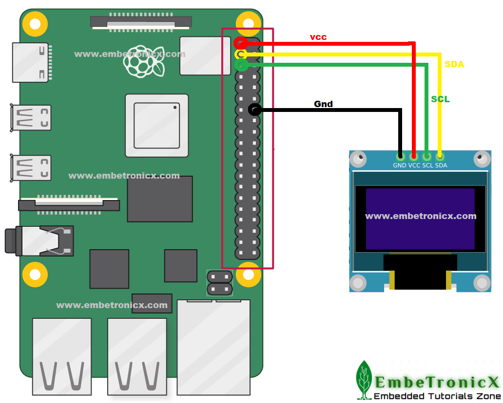
Please enable the I2C in the Raspberry Pi.
If you see the Pinout of the Raspberry Pi 4,
- GPIO 2 – SDA
- GPIO 3 – SCL
Connection Diagram
Driver Source Code
If you want to interface any other I2C slave, then you don’t care about the functions that start with SSD1306_. You implement your own functions for that slave.
[Get the source code from the GitHub]
/***************************************************************************//**
*  file       driver.c
*
*  details    Simple I2C driver explanation (SSD_1306 OLED Display Interface)
*
*  author     EmbeTronicX
*
*  Tested with Linux raspberrypi 5.4.51-v7l+
*
* *******************************************************************************/
#include <linux/module.h>
#include <linux/init.h>
#include <linux/slab.h>
#include <linux/i2c.h>
#include <linux/delay.h>
#include <linux/kernel.h>

#define I2C_BUS_AVAILABLE   (          1 )              // I2C Bus available in our Raspberry Pi
#define SLAVE_DEVICE_NAME   ( "ETX_OLED" )              // Device and Driver Name
#define SSD1306_SLAVE_ADDR  (       0x3C )              // SSD1306 OLED Slave Address

static struct i2c_adapter *etx_i2c_adapter     = NULL;  // I2C Adapter Structure
static struct i2c_client  *etx_i2c_client_oled = NULL;  // I2C Cient Structure (In our case it is OLED)

/*
** This function writes the data into the I2C client
**
**  Arguments:
**      buff -> buffer to be sent
**      len  -> Length of the data
**
*/
static int I2C_Write(unsigned char *buf, unsigned int len)
{
    /*
    ** Sending Start condition, Slave address with R/W bit,
    ** ACK/NACK and Stop condtions will be handled internally.
    */
    int ret = i2c_master_send(etx_i2c_client_oled, buf, len);

    return ret;
}

/*
** This function reads one byte of the data from the I2C client
**
**  Arguments:
**      out_buff -> buffer wherer the data to be copied
**      len      -> Length of the data to be read
**
*/
static int I2C_Read(unsigned char *out_buf, unsigned int len)
{
    /*
    ** Sending Start condition, Slave address with R/W bit,
    ** ACK/NACK and Stop condtions will be handled internally.
    */
    int ret = i2c_master_recv(etx_i2c_client_oled, out_buf, len);

    return ret;
}

/*
** This function is specific to the SSD_1306 OLED.
** This function sends the command/data to the OLED.
**
**  Arguments:
**      is_cmd -> true = command, flase = data
**      data   -> data to be written
**
*/
static void SSD1306_Write(bool is_cmd, unsigned char data)
{
    unsigned char buf[2] = {0};
    int ret;

    /*
    ** First byte is always control byte. Data is followed after that.
    **
    ** There are two types of data in SSD_1306 OLED.
    ** 1. Command
    ** 2. Data
    **
    ** Control byte decides that the next byte is, command or data.
    **
    ** -------------------------------------------------------
    ** |              Control byte's | 6th bit  |   7th bit  |
    ** |-----------------------------|----------|------------|
    ** |   Command                   |   0      |     0      |
    ** |-----------------------------|----------|------------|
    ** |   data                      |   1      |     0      |
    ** |-----------------------------|----------|------------|
    **
    ** Please refer the datasheet for more information.
    **
    */
    if( is_cmd == true )
    {
        buf[0] = 0x00;
    }
    else
    {
        buf[0] = 0x40;
    }

    buf[1] = data;

    ret = I2C_Write(buf, 2);
}


/*
** This function sends the commands that need to used to Initialize the OLED.
**
**  Arguments:
**      none
**
*/
static int SSD1306_DisplayInit(void)
{
    msleep(100);               // delay

    /*
    ** Commands to initialize the SSD_1306 OLED Display
    */
    SSD1306_Write(true, 0xAE); // Entire Display OFF
    SSD1306_Write(true, 0xD5); // Set Display Clock Divide Ratio and Oscillator Frequency
    SSD1306_Write(true, 0x80); // Default Setting for Display Clock Divide Ratio and Oscillator Frequency that is recommended
    SSD1306_Write(true, 0xA8); // Set Multiplex Ratio
    SSD1306_Write(true, 0x3F); // 64 COM lines
    SSD1306_Write(true, 0xD3); // Set display offset
    SSD1306_Write(true, 0x00); // 0 offset
    SSD1306_Write(true, 0x40); // Set first line as the start line of the display
    SSD1306_Write(true, 0x8D); // Charge pump
    SSD1306_Write(true, 0x14); // Enable charge dump during display on
    SSD1306_Write(true, 0x20); // Set memory addressing mode
    SSD1306_Write(true, 0x00); // Horizontal addressing mode
    SSD1306_Write(true, 0xA1); // Set segment remap with column address 127 mapped to segment 0
    SSD1306_Write(true, 0xC8); // Set com output scan direction, scan from com63 to com 0
    SSD1306_Write(true, 0xDA); // Set com pins hardware configuration
    SSD1306_Write(true, 0x12); // Alternative com pin configuration, disable com left/right remap
    SSD1306_Write(true, 0x81); // Set contrast control
    SSD1306_Write(true, 0x80); // Set Contrast to 128
    SSD1306_Write(true, 0xD9); // Set pre-charge period
    SSD1306_Write(true, 0xF1); // Phase 1 period of 15 DCLK, Phase 2 period of 1 DCLK
    SSD1306_Write(true, 0xDB); // Set Vcomh deselect level
    SSD1306_Write(true, 0x20); // Vcomh deselect level ~ 0.77 Vcc
    SSD1306_Write(true, 0xA4); // Entire display ON, resume to RAM content display
    SSD1306_Write(true, 0xA6); // Set Display in Normal Mode, 1 = ON, 0 = OFF
    SSD1306_Write(true, 0x2E); // Deactivate scroll
    SSD1306_Write(true, 0xAF); // Display ON in normal mode

    return 0;
}

/*
** This function Fills the complete OLED with this data byte.
**
**  Arguments:
**      data  -> Data to be filled in the OLED
**
*/
static void SSD1306_Fill(unsigned char data)
{
    unsigned int total  = 128 * 8;  // 8 pages x 128 segments x 8 bits of data
    unsigned int i      = 0;

    //Fill the Display
    for(i = 0; i < total; i++)
    {
        SSD1306_Write(false, data);
    }
}

/*
** This function getting called when the slave has been found
** Note : This will be called only once when we load the driver.
*/
static int etx_oled_probe(struct i2c_client *client,
                         const struct i2c_device_id *id)
{
    SSD1306_DisplayInit();

    //fill the OLED with this data
    SSD1306_Fill(0xFF);

    pr_info("OLED Probed!!!n");

    return 0;
}

/*
** This function getting called when the slave has been removed
** Note : This will be called only once when we unload the driver.
*/
static int etx_oled_remove(struct i2c_client *client)
{
    //fill the OLED with this data
    SSD1306_Fill(0x00);

    pr_info("OLED Removed!!!n");
    return 0;
}

/*
** Structure that has slave device id
*/
static const struct i2c_device_id etx_oled_id[] = {
        { SLAVE_DEVICE_NAME, 0 },
        { }
};
MODULE_DEVICE_TABLE(i2c, etx_oled_id);

/*
** I2C driver Structure that has to be added to linux
*/
static struct i2c_driver etx_oled_driver = {
        .driver = {
            .name   = SLAVE_DEVICE_NAME,
            .owner  = THIS_MODULE,
        },
        .probe          = etx_oled_probe,
        .remove         = etx_oled_remove,
        .id_table       = etx_oled_id,
};

/*
** I2C Board Info strucutre
*/
static struct i2c_board_info oled_i2c_board_info = {
        I2C_BOARD_INFO(SLAVE_DEVICE_NAME, SSD1306_SLAVE_ADDR)
    };

/*
** Module Init function
*/
static int __init etx_driver_init(void)
{
    int ret = -1;
    etx_i2c_adapter     = i2c_get_adapter(I2C_BUS_AVAILABLE);

    if( etx_i2c_adapter != NULL )
    {
        etx_i2c_client_oled = i2c_new_device(etx_i2c_adapter, &oled_i2c_board_info);

        if( etx_i2c_client_oled != NULL )
        {
            i2c_add_driver(&etx_oled_driver);
            ret = 0;
        }

        i2c_put_adapter(etx_i2c_adapter);
    }

    pr_info("Driver Added!!!n");
    return ret;
}

/*
** Module Exit function
*/
static void __exit etx_driver_exit(void)
{
    i2c_unregister_device(etx_i2c_client_oled);
    i2c_del_driver(&etx_oled_driver);
    pr_info("Driver Removed!!!n");
}

module_init(etx_driver_init);
module_exit(etx_driver_exit);

MODULE_LICENSE("GPL");
MODULE_AUTHOR("EmbeTronicX <[email protected]>");
MODULE_DESCRIPTION("Simple I2C driver explanation (SSD_1306 OLED Display Interface)");
MODULE_VERSION("1.34");
Makefile
obj-m += driver.o

KDIR = /lib/modules/$(shell uname -r)/build


all:
    make -C $(KDIR)  M=$(shell pwd) modules

clean:
    make -C $(KDIR)  M=$(shell pwd) clean
Testing the Device Driver
- Build the driver by using Makefile (
sudo make) - Load the driver using
sudo insmod driver.ko - See the Display is filled.
- Unload the driver using
sudo rmmod driver - See the Display has been cleared
Output Video
Click here if you don’t see the output gif
 In our next tutorial, we will discuss the dummy I2C bus driver.
Please find the other Linux device driver tutorials here.
You can also read the below tutorials.
| Linux Device Driver Tutorials | C Programming Tutorials |
| FreeRTOS Tutorials | NuttX RTOS Tutorials |
| RTX RTOS Tutorials | Interrupts Basics |
| I2C Protocol – Part 1 (Basics) | I2C Protocol – Part 2 (Advanced Topics) |
| STM32 Tutorials | LPC2148 (ARM7) Tutorials |
| PIC16F877A Tutorials | 8051 Tutorials |
| Unit Testing in C Tutorials | ESP32-IDF Tutorials |
| Raspberry Pi Tutorials | Embedded Interview Topics |
| Reset Sequence in ARM Cortex-M4 | BLE Basics |
| VIC and NVIC in ARM | SPI – Serial Peripheral Interface Protocol |
| STM32F7 Bootloader Tutorials | Raspberry PI Pico Tutorials |
| STM32F103 Bootloader Tutorials | RT-Thread RTOS Tutorials |
| Zephyr RTOS Tutorials — STM32 | Zephyr RTOS Tutorials — ESP32 |
| VHDL Tutorials | UDS Protocol Tutorials |
| Product Reviews | STM32 MikroC Bootloader Tutorial |

Embedded Software | Firmware | Linux Devic Deriver | RTOS
Hi, I’m SLR. I am a tech blogger and an Embedded Engineer. I am always eager to learn and explore tech-related stuff! also, I wanted to deliver you the same as much in a more straightforward way with more informative content. I generally appreciate learning by doing, rather than only learning. If you want to help support me on my journey, consider sharing my articles, or Buy me a Coffee! Thank you for reading my blog! Happy learning!
Hits (since 1 July 2022) — 27,544
I’ve been using various I2C things in Linux for the past year and a bit, and I’ve learnt a few things about it from that. Here I hope to collate some of this information.
The Basics
Linux has an i2c subsystem. This provides methods for interacting with I2C clients connected to the same bus as the machine running Linux. As far as I know, Linux can only be a master at the moment. If you’ve got an I2C client that needs to interact with your Linux system then you’ve got two options. The first is to write a driver as a Linux kernel module. This is (surprisingly) straightforward but isn’t what I’m going to focus on here. The second method is to use the “i2c-dev” kernel module. This lets you interact with your devices from userspace and is what I’ll be covering here. If you want to write a kernel driver, then there are good sources of information for this lurking around the place – also have a look in Documentation/i2c/writing-clients in the Linux source.
Preparing your system
The first thing to do is to make sure that the kernel that you’re going to be running this program under has the “I2C device interface” driver either compiled in or as a module. The Linux build config option for this is CONFIG_I2C_CHARDEV. The second thing that you need to make sure you have is the i2c-dev.h header file from the lm-sensors project. For some reason, it took me a whlie to realise that this header file needed to come from there. Download their tarball and find the header somewhere in there. This header file contains some inline functions that wrap around the ioctls of the /dev/i2c-N device files that the i2c-dev kernel driver creates.
When one has both the i2c-dev module and the kernel module for the I2C adapter loaded, a device file called /dev/i2c-0 (or /dev/i2c-1, /dev/i2c-2 etc.) will be created. It’s important to note that it will only be created if you’re running udev. You might need to run:
% mknod /dev/i2c-0 c 89 0
Which will create the device file.
Opening the device
In your program, you’ll need to open the device file for the i2c adapter:
        int fd;
        fd = open( "/dev/i2c-0", O_RDWR );
After checking for opening errors, the next stage is to set the address of the I2C slave that we want to communicate with:
#define ADDRESS 0x38

...

        if( ioctl( fd, I2C_SLAVE, ADDRESS ) < 0 )
        {
                fprintf( stderr, "Failed to set slave address: %mn" );
                return 2;
        }
To get that I2C_SLAVE constant you’ll need to include the i2c-dev.h file I wrote about above.
Operations
So now that we’ve set the address, then only thing that remains is to actually interact with the device. There are two ways of doing this:
- Using read() and write(). Every time you do one of these an entire I2C transaction takes place (i.e. start bit, address, data, stop).
- Using the wrapper functions that i2c-dev.h provides.
The read() and write() method is fairly straightforward so I won’t go over it here. i2c-dev.h provides many functions to do various i2c transactions. I’ll go over them in a moment — first I’ll provide an example of how to write a single byte to the I2C client:
    if( i2c_smbus_write_byte( fd, 0xAA ) < 0 )
        fprintf( stderr, "Failed to write 0xAA to I2C device: %mn" );
This example writes the byte 0xAA to whatever address was configured using the I2C_SLAVE ioctl. All of the functions in i2c-dev.h will return a number less than 0 upon failure. errno will get set accordingly.
SMBus functions
SMBus is a protocol that defines a set of ways for using an I2C bus. i2c-dev.h provides a function for each of these operations. The best place to read about these is in the SMBus spec in section 5.5 «Bus Protocols» — it has nice pictures.
- i2c_smbus_write_quick( int file, __u8 value)
- i2c_smbus_read_byte(int file)
- i2c_smbus_write_byte(int file, __u8 value)
- i2c_smbus_read_byte_data(int file, __u8 command)
- i2c_smbus_write_byte_data(int file, __u8 command, __u8 value)
- i2c_smbus_read_word_data(int file, __u8 command)
- i2c_smbus_write_word_data(int file, __u8 command, __u16 value)
- i2c_smbus_process_call(int file, __u8 command, __u16 value)
- i2c_smbus_read_block_data(int file, __u8 command, __u8 *values)
- i2c_smbus_write_block_data(int file, __u8 command, __u8 length, __u8 *values)
- i2c_smbus_read_i2c_block_data(int file, __u8 command, __u8 *values)
- i2c_smbus_write_i2c_block_data(int file, __u8 command, __u8 length, __u8 *values)
- i2c_smbus_block_process_call(int file, __u8 command, __u8 length, __u8 *values)
Given the SMBus spec and the list of functions, it’s quite easy to decide what each of them does. If you’re in any doubt, then look for comments in i2c-dev.h around the function. Some of the functions above read data that’s less than 32 bits in length yet return a 32 bit number. This is so that an error can be returned. If the returned value is 0 or above then just cast it into a type of the correct size.
Gotchas
During development, there were a few things that caught me out. I also introduced a couple of other people into using this interface and they got caught out by some things too. Hopefully I’ll assist some others by listing those problems here.
The i2c-dev.h header file
The i2c-dev.h header file comes from the lm-sensors project. You’ll need to grab this from their source.
I2C addresses are 7 bits wide
Apart from the rare 10-bit I2C addressing that some devices employ, all I2C addresses are 7 bits wide. Until I discovered the error of my ways, I would write addresses down as the 7-bit number shifted left by one bit to create an 8-bit word. Basically all I2C devices that do address encoding/detection (including the Linux Kernel) take the address as a 7-bit number.
So if your I2C address was all ‘1’s, you would write it as 0x7F — not 0xFE.
Load the modules
There’s almost always this short period just after I’ve booted a LInux device in which I’ll try to use I2 but nothing will work. Then I remember that I need to load the right modules — the one for the I2C controller itself and i2c-dev for the userspace interface. I know it’s simple, but for some reason I always forget.
Use Checksums
Always use checksums. SMBus already defines a method of generating checksums. They’re also supported by the Linux kernel. You can enable them using an ioctl:
        if( ioctl( fd, I2C_PEC, 1) < 0)

        {

                fprintf( stderr, "Failed to enable PECn");

                return -1;

        }
Disable them by changing the argument to the ioctl to 0.
Block transfers
After painstakingly implementing SMBus block read/write on my I2C client, I discovered that the SMBus block transfers weren’t supported by the I2C driver for my machine’s adapter. So always check that the I2C driver supports the types of transfer that you want to do using the I2C_FUNCS ioctl.
The Linux kernel documentation
The documentation in the /Documentation/i2c directory of the Linux source is a good source of information about using I2C under Linux.
Examples
You want examples? Ok. My Student Robotics colleagues and I have been writing various test utilities that you might like to have a look at. I’m not guaranteeing that they work of course!
I hope this was helpful. I’d be most interested in hearing any feedback that you have.
Posted at 2:55 am on Sunday 11th November 2007
Tags: electronics, i2c, linux
Site by Rob Gilton. © 2008 — 2019
This is a small guide for those who want to write kernel drivers for I2C
or SMBus devices, using Linux as the protocol host/master (not slave).
To set up a driver, you need to do several things. Some are optional, and
some things can be done slightly or completely different. Use this as a
guide, not as a rule book!
The driver structure
Usually, you will implement a single driver structure, and instantiate
all clients from it. Remember, a driver structure contains general access
routines, and should be zero-initialized except for fields with data you
provide. A client structure holds device-specific information like the
driver model device node, and its I2C address.
static struct i2c_device_id foo_idtable[] = {
      { "foo", my_id_for_foo },
      { "bar", my_id_for_bar },
      { }
};

MODULE_DEVICE_TABLE(i2c, foo_idtable);

static struct i2c_driver foo_driver = {
      .driver = {
              .name   = "foo",
              .pm     = &foo_pm_ops,  /* optional */
      },

      .id_table       = foo_idtable,
      .probe          = foo_probe,
      .remove         = foo_remove,
      /* if device autodetection is needed: */
      .class          = I2C_CLASS_SOMETHING,
      .detect         = foo_detect,
      .address_list   = normal_i2c,

      .shutdown       = foo_shutdown, /* optional */
      .command        = foo_command,  /* optional, deprecated */
}
The name field is the driver name, and must not contain spaces. It
should match the module name (if the driver can be compiled as a module),
although you can use MODULE_ALIAS (passing “foo” in this example) to add
another name for the module. If the driver name doesn’t match the module
name, the module won’t be automatically loaded (hotplug/coldplug).
All other fields are for call-back functions which will be explained
below.
Accessing the client
Let’s say we have a valid client structure. At some time, we will need
to gather information from the client, or write new information to the
client.
I have found it useful to define foo_read and foo_write functions for this.
For some cases, it will be easier to call the I2C functions directly,
but many chips have some kind of register-value idea that can easily
be encapsulated.
The below functions are simple examples, and should not be copied
literally:
int foo_read_value(struct i2c_client *client, u8 reg)
{
      if (reg < 0x10) /* byte-sized register */
              return i2c_smbus_read_byte_data(client, reg);
      else            /* word-sized register */
              return i2c_smbus_read_word_data(client, reg);
}

int foo_write_value(struct i2c_client *client, u8 reg, u16 value)
{
      if (reg == 0x10)        /* Impossible to write - driver error! */
              return -EINVAL;
      else if (reg < 0x10)    /* byte-sized register */
              return i2c_smbus_write_byte_data(client, reg, value);
      else                    /* word-sized register */
              return i2c_smbus_write_word_data(client, reg, value);
}
Probing and attaching
The Linux I2C stack was originally written to support access to hardware
monitoring chips on PC motherboards, and thus used to embed some assumptions
that were more appropriate to SMBus (and PCs) than to I2C. One of these
assumptions was that most adapters and devices drivers support the SMBUS_QUICK
protocol to probe device presence. Another was that devices and their drivers
can be sufficiently configured using only such probe primitives.
As Linux and its I2C stack became more widely used in embedded systems
and complex components such as DVB adapters, those assumptions became more
problematic. Drivers for I2C devices that issue interrupts need more (and
different) configuration information, as do drivers handling chip variants
that can’t be distinguished by protocol probing, or which need some board
specific information to operate correctly.
Device/Driver Binding
System infrastructure, typically board-specific initialization code or
boot firmware, reports what I2C devices exist. For example, there may be
a table, in the kernel or from the boot loader, identifying I2C devices
and linking them to board-specific configuration information about IRQs
and other wiring artifacts, chip type, and so on. That could be used to
create i2c_client objects for each I2C device.
I2C device drivers using this binding model work just like any other
kind of driver in Linux: they provide a probe() method to bind to
those devices, and a remove() method to unbind.
static int foo_probe(struct i2c_client *client,
                     const struct i2c_device_id *id);
static int foo_remove(struct i2c_client *client);
Remember that the i2c_driver does not create those client handles. The
handle may be used during foo_probe(). If foo_probe() reports success
(zero not a negative status code) it may save the handle and use it until
foo_remove() returns. That binding model is used by most Linux drivers.
The probe function is called when an entry in the id_table name field
matches the device’s name. It is passed the entry that was matched so
the driver knows which one in the table matched.
Device Creation
If you know for a fact that an I2C device is connected to a given I2C bus,
you can instantiate that device by simply filling an i2c_board_info
structure with the device address and driver name, and calling
i2c_new_client_device(). This will create the device, then the driver core
will take care of finding the right driver and will call its probe() method.
If a driver supports different device types, you can specify the type you
want using the type field. You can also specify an IRQ and platform data
if needed.
Sometimes you know that a device is connected to a given I2C bus, but you
don’t know the exact address it uses. This happens on TV adapters for
example, where the same driver supports dozens of slightly different
models, and I2C device addresses change from one model to the next. In
that case, you can use the i2c_new_scanned_device() variant, which is
similar to i2c_new_client_device(), except that it takes an additional list
of possible I2C addresses to probe. A device is created for the first
responsive address in the list. If you expect more than one device to be
present in the address range, simply call i2c_new_scanned_device() that
many times.
The call to i2c_new_client_device() or i2c_new_scanned_device() typically
happens in the I2C bus driver. You may want to save the returned i2c_client
reference for later use.
Device Detection
Sometimes you do not know in advance which I2C devices are connected to
a given I2C bus. This is for example the case of hardware monitoring
devices on a PC’s SMBus. In that case, you may want to let your driver
detect supported devices automatically. This is how the legacy model
was working, and is now available as an extension to the standard
driver model.
You simply have to define a detect callback which will attempt to
identify supported devices (returning 0 for supported ones and -ENODEV
for unsupported ones), a list of addresses to probe, and a device type
(or class) so that only I2C buses which may have that type of device
connected (and not otherwise enumerated) will be probed. For example,
a driver for a hardware monitoring chip for which auto-detection is
needed would set its class to I2C_CLASS_HWMON, and only I2C adapters
with a class including I2C_CLASS_HWMON would be probed by this driver.
Note that the absence of matching classes does not prevent the use of
a device of that type on the given I2C adapter. All it prevents is
auto-detection; explicit instantiation of devices is still possible.
Note that this mechanism is purely optional and not suitable for all
devices. You need some reliable way to identify the supported devices
(typically using device-specific, dedicated identification registers),
otherwise misdetections are likely to occur and things can get wrong
quickly. Keep in mind that the I2C protocol doesn’t include any
standard way to detect the presence of a chip at a given address, let
alone a standard way to identify devices. Even worse is the lack of
semantics associated to bus transfers, which means that the same
transfer can be seen as a read operation by a chip and as a write
operation by another chip. For these reasons, explicit device
instantiation should always be preferred to auto-detection where
possible.
Device Deletion
Each I2C device which has been created using i2c_new_client_device()
or i2c_new_scanned_device() can be unregistered by calling
i2c_unregister_device(). If you don’t call it explicitly, it will be
called automatically before the underlying I2C bus itself is removed,
as a device can’t survive its parent in the device driver model.
Initializing the driver
When the kernel is booted, or when your foo driver module is inserted,
you have to do some initializing. Fortunately, just registering the
driver module is usually enough.
static int __init foo_init(void)
{
      return i2c_add_driver(&foo_driver);
}
module_init(foo_init);

static void __exit foo_cleanup(void)
{
      i2c_del_driver(&foo_driver);
}
module_exit(foo_cleanup);

The module_i2c_driver() macro can be used to reduce above code.

module_i2c_driver(foo_driver);
Note that some functions are marked by __init. These functions can
be removed after kernel booting (or module loading) is completed.
Likewise, functions marked by __exit are dropped by the compiler when
the code is built into the kernel, as they would never be called.
Driver Information
/* Substitute your own name and email address */
MODULE_AUTHOR("Frodo Looijaard <frodol@dds.nl>"
MODULE_DESCRIPTION("Driver for Barf Inc. Foo I2C devices");

/* a few non-GPL license types are also allowed */
MODULE_LICENSE("GPL");
Power Management
If your I2C device needs special handling when entering a system low
power state – like putting a transceiver into a low power mode, or
activating a system wakeup mechanism – do that by implementing the
appropriate callbacks for the dev_pm_ops of the driver (like suspend
and resume).
These are standard driver model calls, and they work just like they
would for any other driver stack. The calls can sleep, and can use
I2C messaging to the device being suspended or resumed (since their
parent I2C adapter is active when these calls are issued, and IRQs
are still enabled).
System Shutdown
If your I2C device needs special handling when the system shuts down
or reboots (including kexec) – like turning something off – use a
shutdown() method.
Again, this is a standard driver model call, working just like it
would for any other driver stack: the calls can sleep, and can use
I2C messaging.
Command function
A generic ioctl-like function call back is supported. You will seldom
need this, and its use is deprecated anyway, so newer design should not
use it.
Sending and receiving
If you want to communicate with your device, there are several functions
to do this. You can find all of them in <linux/i2c.h>.
If you can choose between plain I2C communication and SMBus level
communication, please use the latter. All adapters understand SMBus level
commands, but only some of them understand plain I2C!
Plain I2C communication
int i2c_master_send(struct i2c_client *client, const char *buf,
                    int count);
int i2c_master_recv(struct i2c_client *client, char *buf, int count);
These routines read and write some bytes from/to a client. The client
contains the I2C address, so you do not have to include it. The second
parameter contains the bytes to read/write, the third the number of bytes
to read/write (must be less than the length of the buffer, also should be
less than 64k since msg.len is u16.) Returned is the actual number of bytes
read/written.
int i2c_transfer(struct i2c_adapter *adap, struct i2c_msg *msg,
                 int num);
This sends a series of messages. Each message can be a read or write,
and they can be mixed in any way. The transactions are combined: no
stop condition is issued between transaction. The i2c_msg structure
contains for each message the client address, the number of bytes of the
message and the message data itself.
You can read the file i2c-protocol for more information about the
actual I2C protocol.
SMBus communication
s32 i2c_smbus_xfer(struct i2c_adapter *adapter, u16 addr,
                   unsigned short flags, char read_write, u8 command,
                   int size, union i2c_smbus_data *data);
This is the generic SMBus function. All functions below are implemented
in terms of it. Never use this function directly!
s32 i2c_smbus_read_byte(struct i2c_client *client);
s32 i2c_smbus_write_byte(struct i2c_client *client, u8 value);
s32 i2c_smbus_read_byte_data(struct i2c_client *client, u8 command);
s32 i2c_smbus_write_byte_data(struct i2c_client *client,
                              u8 command, u8 value);
s32 i2c_smbus_read_word_data(struct i2c_client *client, u8 command);
s32 i2c_smbus_write_word_data(struct i2c_client *client,
                              u8 command, u16 value);
s32 i2c_smbus_read_block_data(struct i2c_client *client,
                              u8 command, u8 *values);
s32 i2c_smbus_write_block_data(struct i2c_client *client,
                               u8 command, u8 length, const u8 *values);
s32 i2c_smbus_read_i2c_block_data(struct i2c_client *client,
                                  u8 command, u8 length, u8 *values);
s32 i2c_smbus_write_i2c_block_data(struct i2c_client *client,
                                   u8 command, u8 length,
                                   const u8 *values);
These ones were removed from i2c-core because they had no users, but could
be added back later if needed:
s32 i2c_smbus_write_quick(struct i2c_client *client, u8 value);
s32 i2c_smbus_process_call(struct i2c_client *client,
                           u8 command, u16 value);
s32 i2c_smbus_block_process_call(struct i2c_client *client,
                                 u8 command, u8 length, u8 *values);
All these transactions return a negative errno value on failure. The ‘write’
transactions return 0 on success; the ‘read’ transactions return the read
value, except for block transactions, which return the number of values
read. The block buffers need not be longer than 32 bytes.
You can read the file smbus-protocol for more information about the
actual SMBus protocol.
General purpose routines
Below all general purpose routines are listed, that were not mentioned
before:
/* Return the adapter number for a specific adapter */
int i2c_adapter_id(struct i2c_adapter *adap);
The following code will read a byte from position 0x10, of the register at 0x3f of the device /dev/i2c-2.
To compile this code, you need the helper library i2c-dev.h which can be found in the download package here:
Reading data from /dev/i2c-2 Full C Example (Compressed) (1410 downloads)
main.c
//Based on https://www.kernel.org/doc/Documentation/i2c/dev-interface

#include "linux/i2c-dev.h"
#include <stdio.h>
#include <stdlib.h>
#include <fcntl.h>
#include <errno.h>

int main() {
    const int adapter_nr = 2;
    char filename[20];
    snprintf(filename, 19, "/dev/i2c-%d", adapter_nr);
    const int file = open(filename, O_RDWR);
    if (file < 0) {
        printf("Oh dear, something went wrong with open()! %sn", strerror(errno));
        exit(EXIT_FAILURE);
    }

    // The I2C address. Got it from `i2cdetect -y 2;`
    const int addr = 0x3f;

    if (ioctl(file, I2C_SLAVE, addr) < 0) {
        printf("Oh dear, something went wrong with ioctl()! %sn", strerror(errno));
        exit(EXIT_FAILURE);
    }

    // Device register to access.
    const __u8 reg = 0x10;
    // Using SMBus commands
    const __s32 result = i2c_smbus_read_byte_data(file, reg);
    if (result < 0) {
         // ERROR HANDLING: i2c transaction failed
         printf("Oh dear, something went wrong with i2c_smbus_read_byte_data()>i2c_smbus_access()>ioctl()! %sn", strerror(errno));
        exit(EXIT_FAILURE);
    } else {
        // res contains the read word
        printf("0x%+02xn", result);
    }

    close(file);

    return(EXIT_SUCCESS);
}
linux/i2c-dev.h
/*
    i2c-dev.h - i2c-bus driver, char device interface

    Copyright (C) 1995-97 Simon G. Vogl
    Copyright (C) 1998-99 Frodo Looijaard <[email protected]>

    This program is free software; you can redistribute it and/or modify
    it under the terms of the GNU General Public License as published by
    the Free Software Foundation; either version 2 of the License, or
    (at your option) any later version.

    This program is distributed in the hope that it will be useful,
    but WITHOUT ANY WARRANTY; without even the implied warranty of
    MERCHANTABILITY or FITNESS FOR A PARTICULAR PURPOSE.  See the
    GNU General Public License for more details.

    You should have received a copy of the GNU General Public License
    along with this program; if not, write to the Free Software
    Foundation, Inc., 51 Franklin Street, Fifth Floor, Boston,
    MA 02110-1301 USA.
*/

#ifndef _LINUX_I2C_DEV_H
#define _LINUX_I2C_DEV_H

#include <linux/types.h>
#include <sys/ioctl.h>
#include <stddef.h>


/* -- i2c.h -- */


/*
 * I2C Message - used for pure i2c transaction, also from /dev interface
 */
struct i2c_msg {
    __u16 addr;    /* slave address            */
    unsigned short flags;
#define I2C_M_TEN    0x10    /* we have a ten bit chip address    */
#define I2C_M_RD    0x01
#define I2C_M_NOSTART    0x4000
#define I2C_M_REV_DIR_ADDR    0x2000
#define I2C_M_IGNORE_NAK    0x1000
#define I2C_M_NO_RD_ACK        0x0800
    short len;        /* msg length                */
    char *buf;        /* pointer to msg data            */
};

/* To determine what functionality is present */

#define I2C_FUNC_I2C            0x00000001
#define I2C_FUNC_10BIT_ADDR        0x00000002
#define I2C_FUNC_PROTOCOL_MANGLING    0x00000004 /* I2C_M_{REV_DIR_ADDR,NOSTART,..} */
#define I2C_FUNC_SMBUS_PEC        0x00000008
#define I2C_FUNC_SMBUS_BLOCK_PROC_CALL    0x00008000 /* SMBus 2.0 */
#define I2C_FUNC_SMBUS_QUICK        0x00010000
#define I2C_FUNC_SMBUS_READ_BYTE    0x00020000
#define I2C_FUNC_SMBUS_WRITE_BYTE    0x00040000
#define I2C_FUNC_SMBUS_READ_BYTE_DATA    0x00080000
#define I2C_FUNC_SMBUS_WRITE_BYTE_DATA    0x00100000
#define I2C_FUNC_SMBUS_READ_WORD_DATA    0x00200000
#define I2C_FUNC_SMBUS_WRITE_WORD_DATA    0x00400000
#define I2C_FUNC_SMBUS_PROC_CALL    0x00800000
#define I2C_FUNC_SMBUS_READ_BLOCK_DATA    0x01000000
#define I2C_FUNC_SMBUS_WRITE_BLOCK_DATA 0x02000000
#define I2C_FUNC_SMBUS_READ_I2C_BLOCK    0x04000000 /* I2C-like block xfer  */
#define I2C_FUNC_SMBUS_WRITE_I2C_BLOCK    0x08000000 /* w/ 1-byte reg. addr. */

#define I2C_FUNC_SMBUS_BYTE (I2C_FUNC_SMBUS_READ_BYTE |
                             I2C_FUNC_SMBUS_WRITE_BYTE)
#define I2C_FUNC_SMBUS_BYTE_DATA (I2C_FUNC_SMBUS_READ_BYTE_DATA |
                                  I2C_FUNC_SMBUS_WRITE_BYTE_DATA)
#define I2C_FUNC_SMBUS_WORD_DATA (I2C_FUNC_SMBUS_READ_WORD_DATA |
                                  I2C_FUNC_SMBUS_WRITE_WORD_DATA)
#define I2C_FUNC_SMBUS_BLOCK_DATA (I2C_FUNC_SMBUS_READ_BLOCK_DATA |
                                   I2C_FUNC_SMBUS_WRITE_BLOCK_DATA)
#define I2C_FUNC_SMBUS_I2C_BLOCK (I2C_FUNC_SMBUS_READ_I2C_BLOCK |
                                  I2C_FUNC_SMBUS_WRITE_I2C_BLOCK)

/* Old name, for compatibility */
#define I2C_FUNC_SMBUS_HWPEC_CALC    I2C_FUNC_SMBUS_PEC

/*
 * Data for SMBus Messages
 */
#define I2C_SMBUS_BLOCK_MAX    32    /* As specified in SMBus standard */
#define I2C_SMBUS_I2C_BLOCK_MAX    32    /* Not specified but we use same structure */
union i2c_smbus_data {
    __u8 byte;
    __u16 word;
    __u8 block[I2C_SMBUS_BLOCK_MAX + 2]; /* block[0] is used for length */
                                                /* and one more for PEC */
};

/* smbus_access read or write markers */
#define I2C_SMBUS_READ    1
#define I2C_SMBUS_WRITE    0

/* SMBus transaction types (size parameter in the above functions)
   Note: these no longer correspond to the (arbitrary) PIIX4 internal codes! */
#define I2C_SMBUS_QUICK            0
#define I2C_SMBUS_BYTE            1
#define I2C_SMBUS_BYTE_DATA        2
#define I2C_SMBUS_WORD_DATA        3
#define I2C_SMBUS_PROC_CALL        4
#define I2C_SMBUS_BLOCK_DATA        5
#define I2C_SMBUS_I2C_BLOCK_BROKEN  6
#define I2C_SMBUS_BLOCK_PROC_CALL   7        /* SMBus 2.0 */
#define I2C_SMBUS_I2C_BLOCK_DATA    8


/* /dev/i2c-X ioctl commands.  The ioctl's parameter is always an
 * unsigned long, except for:
 *    - I2C_FUNCS, takes pointer to an unsigned long
 *    - I2C_RDWR, takes pointer to struct i2c_rdwr_ioctl_data
 *    - I2C_SMBUS, takes pointer to struct i2c_smbus_ioctl_data
 */
#define I2C_RETRIES    0x0701    /* number of times a device address should
                   be polled when not acknowledging */
#define I2C_TIMEOUT    0x0702    /* set timeout in units of 10 ms */

/* NOTE: Slave address is 7 or 10 bits, but 10-bit addresses
 * are NOT supported! (due to code brokenness)
 */
#define I2C_SLAVE    0x0703    /* Use this slave address */
#define I2C_SLAVE_FORCE    0x0706    /* Use this slave address, even if it
                   is already in use by a driver! */
#define I2C_TENBIT    0x0704    /* 0 for 7 bit addrs, != 0 for 10 bit */

#define I2C_FUNCS    0x0705    /* Get the adapter functionality mask */

#define I2C_RDWR    0x0707    /* Combined R/W transfer (one STOP only) */

#define I2C_PEC        0x0708    /* != 0 to use PEC with SMBus */
#define I2C_SMBUS    0x0720    /* SMBus transfer */


/* This is the structure as used in the I2C_SMBUS ioctl call */
struct i2c_smbus_ioctl_data {
    __u8 read_write;
    __u8 command;
    __u32 size;
    union i2c_smbus_data *data;
};

/* This is the structure as used in the I2C_RDWR ioctl call */
struct i2c_rdwr_ioctl_data {
    struct i2c_msg *msgs;    /* pointers to i2c_msgs */
    __u32 nmsgs;            /* number of i2c_msgs */
};

#define  I2C_RDRW_IOCTL_MAX_MSGS    42


static inline __s32 i2c_smbus_access(int file, char read_write, __u8 command,
                                     int size, union i2c_smbus_data *data)
{
    struct i2c_smbus_ioctl_data args;

    args.read_write = read_write;
    args.command = command;
    args.size = size;
    args.data = data;
    return ioctl(file,I2C_SMBUS,&args);
}


static inline __s32 i2c_smbus_write_quick(int file, __u8 value)
{
    return i2c_smbus_access(file,value,0,I2C_SMBUS_QUICK,NULL);
}

static inline __s32 i2c_smbus_read_byte(int file)
{
    union i2c_smbus_data data;
    if (i2c_smbus_access(file,I2C_SMBUS_READ,0,I2C_SMBUS_BYTE,&data))
        return -1;
    else
        return 0x0FF & data.byte;
}

static inline __s32 i2c_smbus_write_byte(int file, __u8 value)
{
    return i2c_smbus_access(file,I2C_SMBUS_WRITE,value,
                            I2C_SMBUS_BYTE,NULL);
}

static inline __s32 i2c_smbus_read_byte_data(int file, __u8 command)
{
    union i2c_smbus_data data;
    if (i2c_smbus_access(file,I2C_SMBUS_READ,command,
                         I2C_SMBUS_BYTE_DATA,&data))
        return -1;
    else
        return 0x0FF & data.byte;
}

static inline __s32 i2c_smbus_write_byte_data(int file, __u8 command,
                                              __u8 value)
{
    union i2c_smbus_data data;
    data.byte = value;
    return i2c_smbus_access(file,I2C_SMBUS_WRITE,command,
                            I2C_SMBUS_BYTE_DATA, &data);
}

static inline __s32 i2c_smbus_read_word_data(int file, __u8 command)
{
    union i2c_smbus_data data;
    if (i2c_smbus_access(file,I2C_SMBUS_READ,command,
                         I2C_SMBUS_WORD_DATA,&data))
        return -1;
    else
        return 0x0FFFF & data.word;
}

static inline __s32 i2c_smbus_write_word_data(int file, __u8 command,
                                              __u16 value)
{
    union i2c_smbus_data data;
    data.word = value;
    return i2c_smbus_access(file,I2C_SMBUS_WRITE,command,
                            I2C_SMBUS_WORD_DATA, &data);
}

static inline __s32 i2c_smbus_process_call(int file, __u8 command, __u16 value)
{
    union i2c_smbus_data data;
    data.word = value;
    if (i2c_smbus_access(file,I2C_SMBUS_WRITE,command,
                         I2C_SMBUS_PROC_CALL,&data))
        return -1;
    else
        return 0x0FFFF & data.word;
}


/* Returns the number of read bytes */
static inline __s32 i2c_smbus_read_block_data(int file, __u8 command,
                                              __u8 *values)
{
    union i2c_smbus_data data;
    int i;
    if (i2c_smbus_access(file,I2C_SMBUS_READ,command,
                         I2C_SMBUS_BLOCK_DATA,&data))
        return -1;
    else {
        for (i = 1; i <= data.block[0]; i++)
            values[i-1] = data.block[i];
        return data.block[0];
    }
}

static inline __s32 i2c_smbus_write_block_data(int file, __u8 command,
                                               __u8 length, const __u8 *values)
{
    union i2c_smbus_data data;
    int i;
    if (length > 32)
        length = 32;
    for (i = 1; i <= length; i++)
        data.block[i] = values[i-1];
    data.block[0] = length;
    return i2c_smbus_access(file,I2C_SMBUS_WRITE,command,
                            I2C_SMBUS_BLOCK_DATA, &data);
}

/* Returns the number of read bytes */
/* Until kernel 2.6.22, the length is hardcoded to 32 bytes. If you
   ask for less than 32 bytes, your code will only work with kernels
   2.6.23 and later. */
static inline __s32 i2c_smbus_read_i2c_block_data(int file, __u8 command,
                                                  __u8 length, __u8 *values)
{
    union i2c_smbus_data data;
    int i;

    if (length > 32)
        length = 32;
    data.block[0] = length;
    if (i2c_smbus_access(file,I2C_SMBUS_READ,command,
                         length == 32 ? I2C_SMBUS_I2C_BLOCK_BROKEN :
                          I2C_SMBUS_I2C_BLOCK_DATA,&data))
        return -1;
    else {
        for (i = 1; i <= data.block[0]; i++)
            values[i-1] = data.block[i];
        return data.block[0];
    }
}

static inline __s32 i2c_smbus_write_i2c_block_data(int file, __u8 command,
                                                   __u8 length,
                                                   const __u8 *values)
{
    union i2c_smbus_data data;
    int i;
    if (length > 32)
        length = 32;
    for (i = 1; i <= length; i++)
        data.block[i] = values[i-1];
    data.block[0] = length;
    return i2c_smbus_access(file,I2C_SMBUS_WRITE,command,
                            I2C_SMBUS_I2C_BLOCK_BROKEN, &data);
}

/* Returns the number of read bytes */
static inline __s32 i2c_smbus_block_process_call(int file, __u8 command,
                                                 __u8 length, __u8 *values)
{
    union i2c_smbus_data data;
    int i;
    if (length > 32)
        length = 32;
    for (i = 1; i <= length; i++)
        data.block[i] = values[i-1];
    data.block[0] = length;
    if (i2c_smbus_access(file,I2C_SMBUS_WRITE,command,
                         I2C_SMBUS_BLOCK_PROC_CALL,&data))
        return -1;
    else {
        for (i = 1; i <= data.block[0]; i++)
            values[i-1] = data.block[i];
        return data.block[0];
    }
}


#endif /* _LINUX_I2C_DEV_H */
This post is also available in:
Greek
Based on kernel version 4.16.1. Page generated on 2018-04-09 11:53 EST.
1	SMBus Protocol Summary
2	======================
3
4	The following is a summary of the SMBus protocol. It applies to
5	all revisions of the protocol (1.0, 1.1, and 2.0).
6	Certain protocol features which are not supported by
7	this package are briefly described at the end of this document.
8
9	Some adapters understand only the SMBus (System Management Bus) protocol,
10	which is a subset from the I2C protocol. Fortunately, many devices use
11	only the same subset, which makes it possible to put them on an SMBus.
12
13	If you write a driver for some I2C device, please try to use the SMBus
14	commands if at all possible (if the device uses only that subset of the
15	I2C protocol). This makes it possible to use the device driver on both
16	SMBus adapters and I2C adapters (the SMBus command set is automatically
17	translated to I2C on I2C adapters, but plain I2C commands can not be
18	handled at all on most pure SMBus adapters).
19
20	Below is a list of SMBus protocol operations, and the functions executing
21	them.  Note that the names used in the SMBus protocol specifications usually
22	don't match these function names.  For some of the operations which pass a
23	single data byte, the functions using SMBus protocol operation names execute
24	a different protocol operation entirely.
25
26	Each transaction type corresponds to a functionality flag. Before calling a
27	transaction function, a device driver should always check (just once) for
28	the corresponding functionality flag to ensure that the underlying I2C
29	adapter supports the transaction in question. See
30	<file:Documentation/i2c/functionality> for the details.
31
32
33	Key to symbols
34	==============
35
36	S     (1 bit) : Start bit
37	P     (1 bit) : Stop bit
38	Rd/Wr (1 bit) : Read/Write bit. Rd equals 1, Wr equals 0.
39	A, NA (1 bit) : Accept and reverse accept bit.
40	Addr  (7 bits): I2C 7 bit address. Note that this can be expanded as usual to
41	                get a 10 bit I2C address.
42	Comm  (8 bits): Command byte, a data byte which often selects a register on
43	                the device.
44	Data  (8 bits): A plain data byte. Sometimes, I write DataLow, DataHigh
45	                for 16 bit data.
46	Count (8 bits): A data byte containing the length of a block operation.
47
48	[..]: Data sent by I2C device, as opposed to data sent by the host adapter.
49
50
51	SMBus Quick Command
52	===================
53
54	This sends a single bit to the device, at the place of the Rd/Wr bit.
55
56	A Addr Rd/Wr [A] P
57
58	Functionality flag: I2C_FUNC_SMBUS_QUICK
59
60
61	SMBus Receive Byte:  i2c_smbus_read_byte()
62	==========================================
63
64	This reads a single byte from a device, without specifying a device
65	register. Some devices are so simple that this interface is enough; for
66	others, it is a shorthand if you want to read the same register as in
67	the previous SMBus command.
68
69	S Addr Rd [A] [Data] NA P
70
71	Functionality flag: I2C_FUNC_SMBUS_READ_BYTE
72
73
74	SMBus Send Byte:  i2c_smbus_write_byte()
75	========================================
76
77	This operation is the reverse of Receive Byte: it sends a single byte
78	to a device.  See Receive Byte for more information.
79
80	S Addr Wr [A] Data [A] P
81
82	Functionality flag: I2C_FUNC_SMBUS_WRITE_BYTE
83
84
85	SMBus Read Byte:  i2c_smbus_read_byte_data()
86	============================================
87
88	This reads a single byte from a device, from a designated register.
89	The register is specified through the Comm byte.
90
91	S Addr Wr [A] Comm [A] S Addr Rd [A] [Data] NA P
92
93	Functionality flag: I2C_FUNC_SMBUS_READ_BYTE_DATA
94
95
96	SMBus Read Word:  i2c_smbus_read_word_data()
97	============================================
98
99	This operation is very like Read Byte; again, data is read from a
100	device, from a designated register that is specified through the Comm
101	byte. But this time, the data is a complete word (16 bits).
102
103	S Addr Wr [A] Comm [A] S Addr Rd [A] [DataLow] A [DataHigh] NA P
104
105	Functionality flag: I2C_FUNC_SMBUS_READ_WORD_DATA
106
107	Note the convenience function i2c_smbus_read_word_swapped is
108	available for reads where the two data bytes are the other way
109	around (not SMBus compliant, but very popular.)
110
111
112	SMBus Write Byte:  i2c_smbus_write_byte_data()
113	==============================================
114
115	This writes a single byte to a device, to a designated register. The
116	register is specified through the Comm byte. This is the opposite of
117	the Read Byte operation.
118
119	S Addr Wr [A] Comm [A] Data [A] P
120
121	Functionality flag: I2C_FUNC_SMBUS_WRITE_BYTE_DATA
122
123
124	SMBus Write Word:  i2c_smbus_write_word_data()
125	==============================================
126
127	This is the opposite of the Read Word operation. 16 bits
128	of data is written to a device, to the designated register that is
129	specified through the Comm byte.
130
131	S Addr Wr [A] Comm [A] DataLow [A] DataHigh [A] P
132
133	Functionality flag: I2C_FUNC_SMBUS_WRITE_WORD_DATA
134
135	Note the convenience function i2c_smbus_write_word_swapped is
136	available for writes where the two data bytes are the other way
137	around (not SMBus compliant, but very popular.)
138
139
140	SMBus Process Call:
141	===================
142
143	This command selects a device register (through the Comm byte), sends
144	16 bits of data to it, and reads 16 bits of data in return.
145
146	S Addr Wr [A] Comm [A] DataLow [A] DataHigh [A]
147	                             S Addr Rd [A] [DataLow] A [DataHigh] NA P
148
149	Functionality flag: I2C_FUNC_SMBUS_PROC_CALL
150
151
152	SMBus Block Read:  i2c_smbus_read_block_data()
153	==============================================
154
155	This command reads a block of up to 32 bytes from a device, from a
156	designated register that is specified through the Comm byte. The amount
157	of data is specified by the device in the Count byte.
158
159	S Addr Wr [A] Comm [A]
160	           S Addr Rd [A] [Count] A [Data] A [Data] A ... A [Data] NA P
161
162	Functionality flag: I2C_FUNC_SMBUS_READ_BLOCK_DATA
163
164
165	SMBus Block Write:  i2c_smbus_write_block_data()
166	================================================
167
168	The opposite of the Block Read command, this writes up to 32 bytes to
169	a device, to a designated register that is specified through the
170	Comm byte. The amount of data is specified in the Count byte.
171
172	S Addr Wr [A] Comm [A] Count [A] Data [A] Data [A] ... [A] Data [A] P
173
174	Functionality flag: I2C_FUNC_SMBUS_WRITE_BLOCK_DATA
175
176
177	SMBus Block Write - Block Read Process Call
178	===========================================
179
180	SMBus Block Write - Block Read Process Call was introduced in
181	Revision 2.0 of the specification.
182
183	This command selects a device register (through the Comm byte), sends
184	1 to 31 bytes of data to it, and reads 1 to 31 bytes of data in return.
185
186	S Addr Wr [A] Comm [A] Count [A] Data [A] ...
187	                             S Addr Rd [A] [Count] A [Data] ... A P
188
189	Functionality flag: I2C_FUNC_SMBUS_BLOCK_PROC_CALL
190
191
192	SMBus Host Notify
193	=================
194
195	This command is sent from a SMBus device acting as a master to the
196	SMBus host acting as a slave.
197	It is the same form as Write Word, with the command code replaced by the
198	alerting device's address.
199
200	[S] [HostAddr] [Wr] A [DevAddr] A [DataLow] A [DataHigh] A [P]
201
202	This is implemented in the following way in the Linux kernel:
203	* I2C bus drivers which support SMBus Host Notify should report
204	  I2C_FUNC_SMBUS_HOST_NOTIFY.
205	* I2C bus drivers trigger SMBus Host Notify by a call to
206	  i2c_handle_smbus_host_notify().
207	* I2C drivers for devices which can trigger SMBus Host Notify will have
208	  client->irq assigned to a Host Notify IRQ if noone else specified an other.
209
210	There is currently no way to retrieve the data parameter from the client.
211
212
213	Packet Error Checking (PEC)
214	===========================
215
216	Packet Error Checking was introduced in Revision 1.1 of the specification.
217
218	PEC adds a CRC-8 error-checking byte to transfers using it, immediately
219	before the terminating STOP.
220
221
222	Address Resolution Protocol (ARP)
223	=================================
224
225	The Address Resolution Protocol was introduced in Revision 2.0 of
226	the specification. It is a higher-layer protocol which uses the
227	messages above.
228
229	ARP adds device enumeration and dynamic address assignment to
230	the protocol. All ARP communications use slave address 0x61 and
231	require PEC checksums.
232
233
234	SMBus Alert
235	===========
236
237	SMBus Alert was introduced in Revision 1.0 of the specification.
238
239	The SMBus alert protocol allows several SMBus slave devices to share a
240	single interrupt pin on the SMBus master, while still allowing the master
241	to know which slave triggered the interrupt.
242
243	This is implemented the following way in the Linux kernel:
244	* I2C bus drivers which support SMBus alert should call
245	  i2c_setup_smbus_alert() to setup SMBus alert support.
246	* I2C drivers for devices which can trigger SMBus alerts should implement
247	  the optional alert() callback.
248
249
250	I2C Block Transactions
251	======================
252
253	The following I2C block transactions are supported by the
254	SMBus layer and are described here for completeness.
255	They are *NOT* defined by the SMBus specification.
256
257	I2C block transactions do not limit the number of bytes transferred
258	but the SMBus layer places a limit of 32 bytes.
259
260
261	I2C Block Read:  i2c_smbus_read_i2c_block_data()
262	================================================
263
264	This command reads a block of bytes from a device, from a
265	designated register that is specified through the Comm byte.
266
267	S Addr Wr [A] Comm [A]
268	           S Addr Rd [A] [Data] A [Data] A ... A [Data] NA P
269
270	Functionality flag: I2C_FUNC_SMBUS_READ_I2C_BLOCK
271
272
273	I2C Block Write:  i2c_smbus_write_i2c_block_data()
274	==================================================
275
276	The opposite of the Block Read command, this writes bytes to
277	a device, to a designated register that is specified through the
278	Comm byte. Note that command lengths of 0, 2, or more bytes are
279	supported as they are indistinguishable from data.
280
281	S Addr Wr [A] Comm [A] Data [A] Data [A] ... [A] Data [A] P
282
283	Functionality flag: I2C_FUNC_SMBUS_WRITE_I2C_BLOCK
- [ i2c ]
- [ busses ]
- dev-interface
- DMA-considerations
- fault-codes
- functionality
- gpio-fault-injection
- i2c-protocol
- i2c-stub
- i2c-topology
- instantiating-devices
- [ muxes ]
- old-module-parameters
- slave-eeprom-backend
- slave-interface
- smbus-protocol
- summary
- ten-bit-addresses
- upgrading-clients
- writing-clients
- Information is copyright its respective author.
- All material is available from the Linux Kernel Source distributed under a GPL License.
- Hosted by mjmwired.net.